hexagon logo

Variation on Cylinder due to probe touching angle


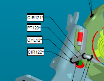
I learned from 101 that for cylinder, the probe should vertical touch the point ( we use analog probe with 2 mm header), the first 3 or 6 even 8 points compose a plane. I believe this definition is good for compensation of the probe header. Now we have a product with an around 5 mm diameter wire which welds on the part. On the drawing the wire could have 2 mm center variation on one workplane. The program measures it as a cylinder( touch 8 points in 180 degree) with a fix angle which I believe has 10 degree away from vertical cut the cylinder (around 80 degree to the plane). I wonder how much variation does this measurement bring it due to my concern and anything we could help reduce those kind of variation?

Thanks
Parents


  • Thank you for the reply. My concern is for cylinder, if the touching is not vertical, after the compensations added on, it could be an oval and no matter which way the software takes to calculate, the center would have some shift. For PC-DMIS, if it does not set the vertical condition for the first plane, in some case( 6 points, 8 points), the cylinder would be not identical.


    If you measure the cylinder directly as either a 'measured cylinder' or a 'auto cylinder' the vectors of each point will all be relative to the vector of the cylinder. I guess a different way to say it is that the software will compensate the hit angles based on the theoretical angle of the cylinder.

    If you prefer to measure 2 of more circles and then construct a cylinder from those, you can run into problems with the vectors not being right if the vectors of your circles are off. A good way to avoid that is to use the CAD to select 'Auto Circles'. Auto circles will define the correct vector no matter what workplane or alignment you are in. Then you can construct a cylinder from those. If you want to make that even more accurate, use the 'BF Recomp' method when constructing the cylinder. That constructs a cylinder using the probe tip center point of each hit and then compensates for the tip radius. It can remove some of the cosine error you may have if the cylinder's angle is off a bit from nominal. That said, the method louisd suggested is more accurate, but admittedly slower.


Reply


  • Thank you for the reply. My concern is for cylinder, if the touching is not vertical, after the compensations added on, it could be an oval and no matter which way the software takes to calculate, the center would have some shift. For PC-DMIS, if it does not set the vertical condition for the first plane, in some case( 6 points, 8 points), the cylinder would be not identical.


    If you measure the cylinder directly as either a 'measured cylinder' or a 'auto cylinder' the vectors of each point will all be relative to the vector of the cylinder. I guess a different way to say it is that the software will compensate the hit angles based on the theoretical angle of the cylinder.

    If you prefer to measure 2 of more circles and then construct a cylinder from those, you can run into problems with the vectors not being right if the vectors of your circles are off. A good way to avoid that is to use the CAD to select 'Auto Circles'. Auto circles will define the correct vector no matter what workplane or alignment you are in. Then you can construct a cylinder from those. If you want to make that even more accurate, use the 'BF Recomp' method when constructing the cylinder. That constructs a cylinder using the probe tip center point of each hit and then compensates for the tip radius. It can remove some of the cosine error you may have if the cylinder's angle is off a bit from nominal. That said, the method louisd suggested is more accurate, but admittedly slower.


Children
  • Correct vectors are required for proper probe comp. IN THE CASE of spheres & cylinders, there is NO probe comp done until the final touch is taken, the sphere or cylinder is constructed AS IF there was no probe comp, THEN Pcdmis comps for the probe radius. The same is mostly true for a circle as well, BUT, the comp is done in a '2D' manner, based upon the theo vector of the circle UNLESS you use 3 surface sample hits, then those are used for the '2D' probe comp.