hexagon logo

Additional MMC

Hey everyone,

I apologize if this seems redundant, I tried looking through the forum first before posting.

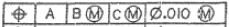
I see quite a few topics about feature control frame call-outs of multiple diameters with MMC and how to apply it in PCDMIS. I'm still not entirely sure I've come across the answer (if I did and someone has that information I'd greatly appreciate it). I've tried a few different ways to apply it, but nothing gets me to the answer I know I should have (based on diameter sizes, etc.). I'm simply looking for the steps on how to apply the additional MMC. The following is what I'm looking to dimension out in PCDMIS.


Any help on this is greatly appreciated. Again, I apologize if this sounds like a redundant question, I'm just really stumped at the moment.

Attached Files
Parents
  • Can you tell us what the datums are?

    I am assuming -A- is a plane...What are -B- & -C-? Are they coaxial holes or are they holes that are going into the face of -A-??

    I use legacy dimensions, if you give me some more info I'll whip up what I would do on the hex block model & share the code
  • Yes -A- is a plane, -B- is center of the part and -C- is a timing hole at a specified radius and angle off the part (~14.02 dia. for -B- and -C- is at R7.400 and angle of 1.5º.

    the visual would be greatly appreciated! I'm struggling to define this correctly in PCDMIS and I know I should be able to get the answer I know is right!
Reply
  • Yes -A- is a plane, -B- is center of the part and -C- is a timing hole at a specified radius and angle off the part (~14.02 dia. for -B- and -C- is at R7.400 and angle of 1.5º.

    the visual would be greatly appreciated! I'm struggling to define this correctly in PCDMIS and I know I should be able to get the answer I know is right!
Children
No Data