hexagon logo

plane to plane distance variable min/max

This should be a quick one for you pros. I have a distance between 2 planes. The max is in tolerance but the min is out. Since using the distance dimension button uses the average, its telling me the feature is in when its not. How do I write a variable for this?
  • This should be a quick one for you pros. I have a distance between 2 planes. The max is in tolerance but the min is out. Since using the distance dimension button uses the average, its telling me the feature is in when its not. How do I write a variable for this?


    This will give the distance between the centroids of each plane. Use point to point distances (opposing points) for a more accurate distance dimension(s). You could then use the eg below to gather the max and min distances. This is accurate.

    ASSIGN/NOM=YOUR DISTANCE
    ASSIGN/V9=ARRAY(D1.MEAS,D2.MEAS,D3.MEAS,D4.MEAS,D5.MEAS,D6.MEAS,D7.MEAS ,D8.MEAS)
    ASSIGN/V10=ABS(NOM-V9)
    ASSIGN/V11=MAXINDEX(V10)
    ASSIGN/V12=V9[V11]
  • It's not so easy, because you have to take a plane as reference, and then dimension the distance between its centroid and each point of the second plane along the vector of the ref.
    If you want to dimension a set of distances point to point, you could create a mid plane, then take points approximately aligned on each plane and dimension the distance along the mid plane vector.
    With a ref, you can
    ASSIGN/V1=DOT(PL1.HIT[1..PL1.NUMHITS].XYZ-PL2.XYZ,PL2.IJK)
    ASSIGN/MAX_DIST=MAX(V1)
    ASSIGN/MIN_DIST=MIN(V1)
    But those distances won't take into account the PL2 flatness...
  • you can directly report min max using
    F10 -> Dimensions -> min max
  • I already do that. But it can't be toleranced that way.
  • Maybe I'll try to talk the customer into profile like it should be. This is a company that usually just assembles parts from other suppliers and don't have a very strong GD&T department. All linear distances. Thanks for your suggestions. I'll also play around with those suggestions and see what works best incase the customer wants to stay simple.
  • Maybe this would be a good addition to future updates since PCDMIS already calculates min and max for a plane to plane distance.
  • you can directly report min max using
    F10 -> Dimensions -> min max


    you can try this

    WORKPLANE/ZPLUS
    PLN2 =FEAT/CONTACT/PLANE/DEFAULT,POLAR,OUTLINE,LEAST_SQR
    THEO/<4.2562,103.565,-0.0341>,<-0.0196617,0.0814898,0.9964802>
    ACTL/<4.2562,103.565,-0.0341>,<-0.0196617,0.0814898,0.9964802>
    TARG/<4.2562,103.565,-0.0341>,<-0.0196617,0.0814898,0.9964802>
    ANGLE VEC=<0.9998054,0,0.0197273>,RADIAL
    SHOW FEATURE PARAMETERS=NO
    SHOW CONTACT PARAMETERS=YES
    NUMHITS=4,NUMROWS=1
    SPACER=6.066
    AVOIDANCE MOVE=NO,DISTANCE=0.3937
    SHOW HITS=NO
    PLN3 =FEAT/CONTACT/PLANE/DEFAULT,POLAR,OUTLINE,LEAST_SQR
    THEO/<2.8668,117.5603,0.45>,<0,0,1>
    ACTL/<2.8668,117.5603,0.45>,<0,0,1>
    TARG/<2.8668,117.5603,0.45>,<0,0,1>
    ANGLE VEC=<1,0,0>,RADIAL
    SHOW FEATURE PARAMETERS=NO
    SHOW CONTACT PARAMETERS=YES
    NUMHITS=4,NUMROWS=1
    SPACER=6.066
    AVOIDANCE MOVE=NO,DISTANCE=0.3937
    SHOW HITS=NO
    DIM DIST9= 3D DISTANCE FROM PLANE PLN2 TO PLANE PLN3,SHORTEST=OFF,NO_RADIUS UNITS=IN,$
    GRAPH=OFF TEXT=OFF MULT=10.00 OUTPUT=NONE
    AX NOMINAL +TOL -TOL MEAS DEV OUTTOL MAX MIN
    M 0.4841 0.0030 0.0030 0.4841 0.0000 0.0000 0.9784 0.0101 --#--
    ASSIGN/VMAX=DIST9.M.MAX
    ASSIGN/VMIN=DIST9.M.MIN
    ASSIGN/NOM=.4841
    FMAX =GENERIC/POINT,DEPENDENT,CARTESIAN,$
    NOM/XYZ,<0,NOM,0>,$
    MEAS/XYZ,<0,VMAX,0>,$
    NOM/IJK,<0,0,1>,$
    MEAS/IJK,<0,0,1>
    DIM LOC39= LOCATION OF POINT FMAX UNITS=IN ,$
    GRAPH=OFF TEXT=OFF MULT=10.00 OUTPUT=BOTH HALF ANGLE=YES
    AX NOMINAL +TOL -TOL MEAS DEV OUTTOL MAX MIN
    Y 0.4841 0.0035 0.0035 0.9784 0.4943 0.4908 0.9784 0.9784 ---->
    END OF DIMENSION LOC39
    FMIN =GENERIC/POINT,DEPENDENT,CARTESIAN,$
    NOM/XYZ,<0,NOM,0>,$
    MEAS/XYZ,<0,VMIN,0>,$
    NOM/IJK,<0,0,1>,$
    MEAS/IJK,<0,0,1>
    DIM LOC40= LOCATION OF POINT FMIN UNITS=IN ,$
    GRAPH=OFF TEXT=OFF MULT=10.00 OUTPUT=BOTH HALF ANGLE=YES
    AX NOMINAL +TOL -TOL MEAS DEV OUTTOL MAX MIN
    Y 0.4841 0.0035 0.0035 0.0101 -0.4740 0.4705 0.0101 0.0101 <----
    END OF DIMENSION LOC40
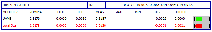
  • Another option to consider is to construct a Width feature from the two planes and then report a Size dimension. There are quite a few reporting options with size dimensions. With the ASME standard you can choose 'opposed points', which reports two separate dimensions. For external widths, one is the max point to point distance and the other is the min distance. If either is out of tolerance it will be highlighted red on the report.

    The reporting looks like this. The top is the Max width. The bottom is the Min width.
    The ISO standard offers even more reporting options, but I can't say much about them as I work mainly with American standards.