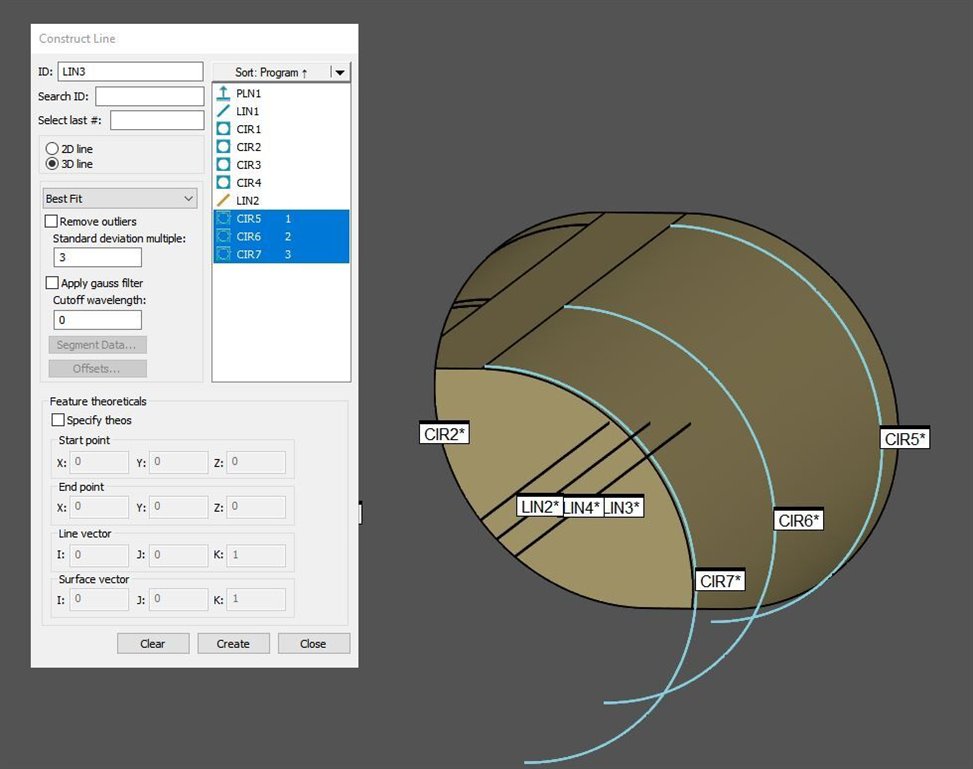
First on each Radius I take 3 levels of circles, create a line and cylinder, Same goes for the other side and then I create a Midline based off of the 2 lines. I then Report the distance between the 2 constructed Cylinders and add radius, make planes for the width and report the distance between the 2 Now on Report output I put none, There's no reason to report it twice. I Then create 2 Generic Cylinders to account for Length and Width using my mid line based off of the condition of the holes and start plugging in the info from all data given. and also under distance in the Generic, Just plug in LIN4.L for the length. This way if a print ask besides position in both directions you can report perpendicularity.
CIR2 =FEAT/CONTACT/CIRCLE/DEFAULT,CARTESIAN,IN,LEAST_SQR
THEO/<0.4243,0.7349,-0.01>,<0,0,1>,0.0937
ACTL/<0.4243,0.7349,-0.01>,<0,0,1>,0.0937
TARG/<0.4243,0.7349,-0.01>,<0,0,1>
START ANG=150,END ANG=330
ANGLE VEC=<1,0,0>
DIRECTION=CCW
SHOW FEATURE PARAMETERS=NO
SHOW CONTACT PARAMETERS=NO

CIR3 =FEAT/CONTACT/CIRCLE/DEFAULT,CARTESIAN,IN,LEAST_SQR
THEO/<0.4243,0.7349,-0.075>,<0,0,1>,0.0937
ACTL/<0.4243,0.7349,-0.075>,<0,0,1>,0.0937
TARG/<0.4243,0.7349,-0.075>,<0,0,1>
START ANG=150,END ANG=330
ANGLE VEC=<1,0,0>
DIRECTION=CCW
SHOW FEATURE PARAMETERS=NO
SHOW CONTACT PARAMETERS=NO

CIR4 =FEAT/CONTACT/CIRCLE/DEFAULT,CARTESIAN,IN,LEAST_SQR
THEO/<0.4243,0.7349,-0.123>,<0,0,1>,0.0937
ACTL/<0.4243,0.7349,-0.123>,<0,0,1>,0.0937
TARG/<0.4243,0.7349,-0.123>,<0,0,1>
START ANG=150,END ANG=330
ANGLE VEC=<1,0,0>
DIRECTION=CCW
SHOW FEATURE PARAMETERS=NO
SHOW CONTACT PARAMETERS=NO

LIN2 =FEAT/LINE,CARTESIAN,UNBOUNDED,NO
THEO/<0.4243,0.7349,-0.01>,<0,0,-1>
ACTL/<0.4243,0.7349,-0.01>,<0,0,-1>
CONSTR/LINE,BF,3D,CIR2,CIR4,CIR3,,
OUTLIER_REMOVAL/OFF,3
FILTER/OFF,WAVELENGTH=0

CIR5 =FEAT/CONTACT/CIRCLE/ADAPTIVE_CIRCLE_SCAN,CARTESIAN,IN,LEAST_SQR
THEO/<0.4343,0.7522,-0.01>,<0,0,1>,0.0938
ACTL/<0.4343,0.7522,-0.01>,<0,0,1>,0.0938
TARG/<0.4343,0.7522,-0.01>,<0,0,1>
START ANG=330,END ANG=510
ANGLE VEC=<1,0,0>
DIRECTION=CCW
SHOW FEATURE PARAMETERS=NO
SHOW CONTACT PARAMETERS=NO

CIR6 =FEAT/CONTACT/CIRCLE/ADAPTIVE_CIRCLE_SCAN,CARTESIAN,IN,LEAST_SQR
THEO/<0.4343,0.7522,-0.075>,<0,0,1>,0.0938
ACTL/<0.4343,0.7522,-0.075>,<0,0,1>,0.0938
TARG/<0.4343,0.7522,-0.075>,<0,0,1>
START ANG=330,END ANG=510
ANGLE VEC=<1,0,0>
DIRECTION=CCW
SHOW FEATURE PARAMETERS=NO
SHOW CONTACT PARAMETERS=NO

CIR7 =FEAT/CONTACT/CIRCLE/ADAPTIVE_CIRCLE_SCAN,CARTESIAN,IN,LEAST_SQR
THEO/<0.4343,0.7522,-0.123>,<0,0,1>,0.0938
ACTL/<0.4343,0.7522,-0.123>,<0,0,1>,0.0938
TARG/<0.4343,0.7522,-0.123>,<0,0,1>
START ANG=330,END ANG=510
ANGLE VEC=<1,0,0>
DIRECTION=CCW
SHOW FEATURE PARAMETERS=NO
SHOW CONTACT PARAMETERS=NO

CYL1 =FEAT/CYLINDER,CARTESIAN,IN,LEAST_SQR,NO
THEO/<0.4243,0.7349,-0.2633>,<0,0,-1>,0.0937,0.113
ACTL/<0.4243,0.7349,-0.2633>,<0,0,-1>,0.0937,0.113
CONSTR/CYLINDER,BF,CIR2,CIR3,CIR4,,

CYL2 =FEAT/CYLINDER,CARTESIAN,IN,LEAST_SQR,NO
THEO/<0.4343,0.7522,-0.0665>,<0,0,-1>,0.0938,0.113
ACTL/<0.4343,0.7522,-0.0665>,<0,0,-1>,0.0938,0.113
CONSTR/CYLINDER,BF,CIR5,CIR6,CIR7,,

DIM DIST3= 3D DISTANCE FROM CYLINDER CYL1 TO CYLINDER CYL2,SHORTEST=OFF,ADD_RADIUS UNITS=IN,$
GRAPH=OFF TEXT=OFF MULT=10.00 OUTPUT=NONE
AX NOMINAL MEAS +TOL -TOL DEV OUTTOL MAX MIN
M 0.1140 0.1137 0.0100 0.0100 -0.0003 0.0000 0.1137 0.1137 ----#----

LIN3 =FEAT/LINE,CARTESIAN,UNBOUNDED,NO
THEO/<0.4343,0.7522,-0.01>,<0,0,-1>
ACTL/<0.4343,0.7522,-0.01>,<0,0,-1>
CONSTR/LINE,BF,3D,CIR5,CIR6,CIR7,,
OUTLIER_REMOVAL/OFF,3
FILTER/OFF,WAVELENGTH=0

LIN4 =FEAT/LINE,CARTESIAN,UNBOUNDED,NO
THEO/<0.4293,0.7435,-0.01>,<0,0,-1>
ACTL/<0.4293,0.7436,-0.01>,<0,0,-1>
CONSTR/LINE,MID,LIN2,LIN3

PLN2 =FEAT/CONTACT/PLANE/DEFAULT,CARTESIAN,OUTLINE,LEAST_SQR
THEO/<0.3872,0.7644,-0.0295>,<0.8660254,-0.5,0>
ACTL/<0.3872,0.7644,-0.0295>,<0.8660259,-0.4999991,0>
TARG/<0.3872,0.7644,-0.0295>,<0.8660254,-0.5,0>
ANGLE VEC=<0,0,-1>,SQUARE
SHOW FEATURE PARAMETERS=NO
SHOW CONTACT PARAMETERS=NO

PLN3 =FEAT/CONTACT/PLANE/DEFAULT,CARTESIAN,OUTLINE,LEAST_SQR
THEO/<0.4688,0.7183,-0.0282>,<-0.8660254,0.5,0>
ACTL/<0.4688,0.7183,-0.0282>,<-0.8660258,0.4999993,0>
TARG/<0.4688,0.7183,-0.0282>,<-0.8660254,0.5,0>
ANGLE VEC=<0,0,1>,SQUARE
SHOW FEATURE PARAMETERS=NO
SHOW CONTACT PARAMETERS=NO

DIM DIST1= 3D DISTANCE FROM PLANE PLN2 TO PLANE PLN3,SHORTEST=OFF,NO_RADIUS UNITS=IN,$
GRAPH=OFF TEXT=OFF MULT=10.00 OUTPUT=NONE
AX NOMINAL MEAS +TOL -TOL DEV OUTTOL MAX MIN
M 0.0937 0.0937 0.0005 0.0005 0.0000 0.0000 0.0937 0.0937 ----#----

WIDTH =GENERIC/CYLINDER,DEPENDENT,CARTESIAN,IN,$
NOM/XYZ,<0.4293,0.7435,-0.01>,$
MEAS/XYZ,<LIN4.X,LIN4.Y,LIN4.Z>,$
NOM/IJK,<0,0,1>,$
MEAS/IJK,<0,0,1>,$
DIAMETER/0.0937,DIST1.MEAS,$
DISTANCE/0.113,LIN4.L

LENGHT =GENERIC/CYLINDER,DEPENDENT,CARTESIAN,OUT,$
NOM/XYZ,<0.4293,0.7435,-0.01>,$
MEAS/XYZ,<LIN4.X,LIN4.Y,LIN4.Z>,$
NOM/IJK,<0,0,1>,$
MEAS/IJK,<0,0,1>,$
DIAMETER/0.114,DIST3.MEAS,$
DISTANCE/0.113,LIN4.L