hexagon logo

PC DMIS Cone position

Can someone explain how PCDMIS gets CONE position values.


I have CONE with 3 levels, all 3 levels (circle0-->2), have different positions values to actual CONE. This is understandable, since its probably looking at AXIS of cone.
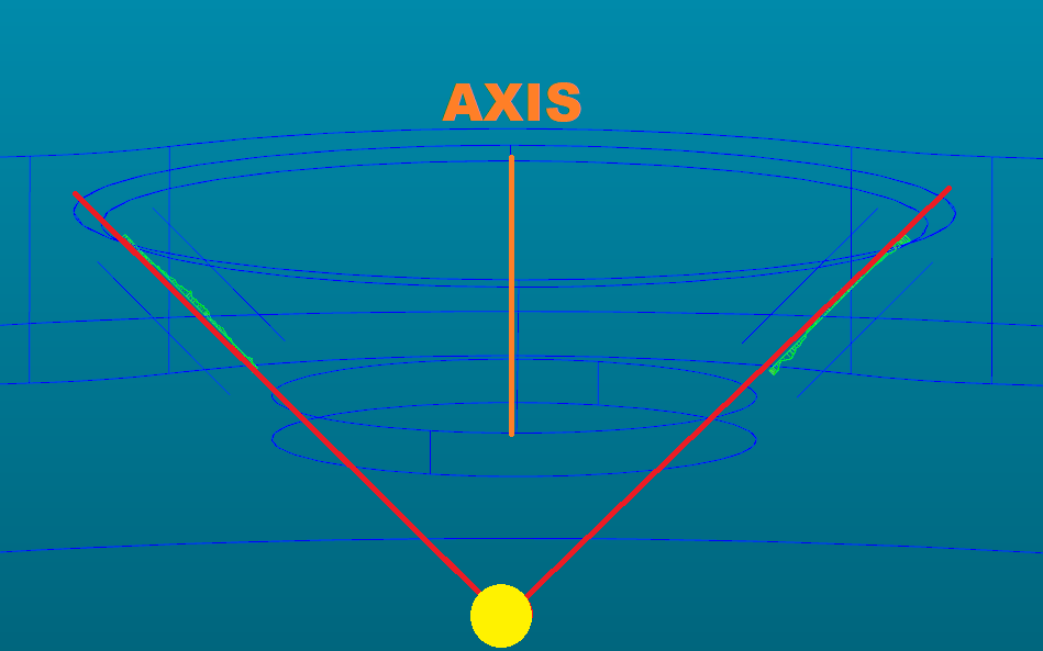


Where in picture above would position of this particular cone be? Also choosing axis average, worst, etc options does not change position values at all.
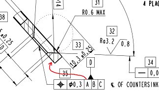


We have instances where position of cone varies by quite alot between measured raw part and finished part. The only difference between raw and finished part is that finished part is grounded to have smooth finish and this also reduces part thickness (so the cone is also cca 20%ish smaller).

Cone position is constrained by datums:
A (bottom plane which is grounded down to have smooth finished, raw part has quite uneven surface)
B (outside diameter, does not change at all)
C (one of the cones on part)
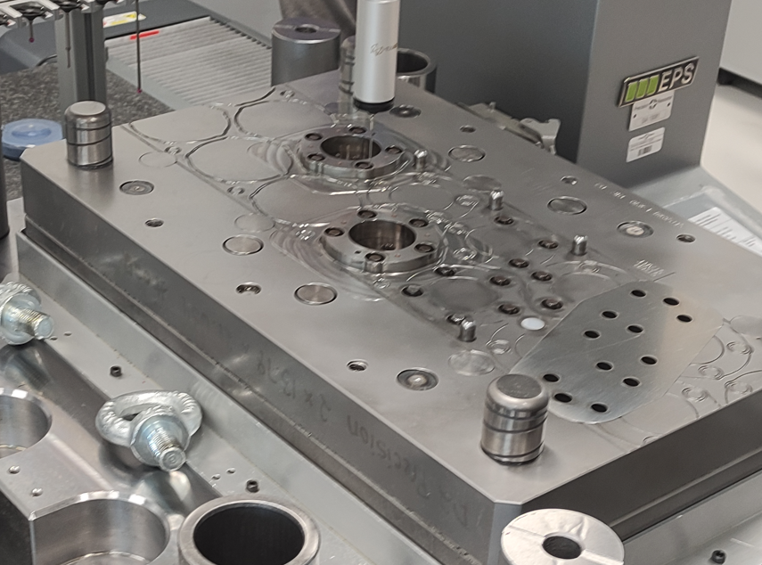


I also measured the tool itself. There are coining punches that make that cone and when I measure position of holes or center of coining punches, all positions look OK within microns. Problem comes when I directly measure position of CONE of those punches. Deviation comes to 0.3mm+.


Thanks in advance for any information you have.


Parents
  • We have a part very very similar to this. Your picture is truncated, but the through holes below the cone have a concentricity callout to the cones, correct?

    How are you probing the cone? Scanning? Touch Trigger Points? Number of points if TTP?

    We have pre-controls in place in which I have a variable that probe goes down to in order to compensate for the grinding process on both sides.

    What I did on the part was actually find the thru holes first. Then when I probe the cones, I zero on the thru holes. I found out that the amount of error on the cones reduced. Then when I spit out the measurements, I dimensioned them the way the print shows. I worked backwards. Maybe try constructing a 3D line from the circles of the cone and see if that helps. I also added a 4th level to the cone in which I saw better repeatability.

    You also have to remember that the cone's axis to taking perpendicularity into account as well. Maybe the progression of the die is not putting the cones in perpendicular. Run a perpendicularity check to see how much that is eating up the tolerance vs the actual position.
Reply
  • We have a part very very similar to this. Your picture is truncated, but the through holes below the cone have a concentricity callout to the cones, correct?

    How are you probing the cone? Scanning? Touch Trigger Points? Number of points if TTP?

    We have pre-controls in place in which I have a variable that probe goes down to in order to compensate for the grinding process on both sides.

    What I did on the part was actually find the thru holes first. Then when I probe the cones, I zero on the thru holes. I found out that the amount of error on the cones reduced. Then when I spit out the measurements, I dimensioned them the way the print shows. I worked backwards. Maybe try constructing a 3D line from the circles of the cone and see if that helps. I also added a 4th level to the cone in which I saw better repeatability.

    You also have to remember that the cone's axis to taking perpendicularity into account as well. Maybe the progression of the die is not putting the cones in perpendicular. Run a perpendicularity check to see how much that is eating up the tolerance vs the actual position.
Children
No Data