hexagon logo

help me measure it, how would u dimension it

hi all
i got a measuring/construction/engineer/noob problem.
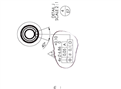
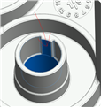
i have this small 40 degree, 2 degree conical thing, that is supposed to have a diameter 6.86mm where it is as smallest, and its supposed to be centered in the casted hole(D), and perpendicular to the plane(A)
i dont know how to measure it, since its a very small surface, and its also not cylindrical, its conical with a 2degree angle.
so i have to measure it as a cone. and then construct a circle using cone feature, but the results are very unsure.

the matching part has the exact same feature, except its internal, and it should run free over the tap thingy.
how can i measure it
or how would u else dimension it, so that the matching part fits.
ty all, thanks for ur feedback

Attached Files
  • Measure the inner diameter as cylinder.
    Level to it and set the origin in it.
    Use auto vector points on the small surface.
    Dimension polar radius from the origin to the vector points.
    Result * 2 should fall within 6.86 (+0.1/-0).

    Make sure you get the polar distance perpendicular to your cylinder so you don't get a 3D distance.

  • hi and ty for helping
    wont the vector points PRAD vary depending where i take the hits (since its conical)
    also how would i get the concentricity call from vector points?

    also the cylinder (big boy hole) is acctually a cone too, (2 degrees). does this matter? (never leveled /orgined to a cone before)
  • Well, if they are conical, measure the big boy hole as cone - or as two circles and create a line between the circles and use that as leveling and origin.

    Normally, when things are conical, the diameter you are looking for is usually set to a gage dimension, either a height/depth on the cone.
    Your snippet does not tell us if that is the case. We don't know if you do have a check distance where the "diameter" should be 6.86.
    Is the 6.86 dimension valid for the entire length or just at a set height?

    The tolerance 0.1 might be so large that it encompasses the length of the cone AND a 2° draft angle (the variation that the 2° draft angle causes is covered by the tolerance).

  • Ok, 6.86 isnt valid for the entire lenght, at the top its around 7.1, at the bottom 6.86. the gage diameter isnt speciefied at any lenght on the drawing, weirdly.
    ive talked with the engineeer and hes open for suggestions, he wouldnt know how to the dimension it. (which is why i also asked how u guys would dimension it to garantuee a fit with matching part)
    but anyway i just agreed we measure the diameter 2mm down from top face, then we measure it the same way on the matching part.
    but measuring it as a cone, gives really bad results for both, diameter, perpendicularity and concentricity, and it varies everytime i measure it. i guess its because the feature surface is too small for analys
    i know theres the FASTRAD algoritm for cirlces/cylinder which gives good results for small arcs, but is there no way to do this with a cone?
  • FIXEDRAD isn't available for cones. You would need to measure two fixed radius circles (one top and one bottom) but you would need to compensate for cosine error.

    From there you could construct an axis (cone) and use the vector point/polar radius method to get the 'diameter'.

    Porfile would probably be a better callout however.
  • how would i compensate for cosine error? (maybe this is question for
    So, if i understand this correctly
    Measure big boy cone, level and orgin to it
    measure two circles on the small arc using fastrad
    compensate for cosine (?)
    construct BF cone using the two circles
    dimension XY for this cone
    orgin to BF cone
    use vector points on small arc
    dimension PRAD

    thanks ninja
  • First, I would construct BFRE cone on circles (it allows to skip cosine error, I think).
    Then, I would measure surface points, and not vector points (for the same reason Slight smile !)
  • I second here, profile would be a better tolerance.
  • The issue is you can't construct a fixed RAD cone - you need to use fixed rad as the variability in diameter/centre point from such a small arc will not produce repeatable results.

    Vector points would have to be given the correct vector, I'd prefer this over the use of surface points as the vector generated off a conical surface by approximation of a plane (even with a very small spacer value) would be less than ideal.
  • why profile?
    And if it were a profile callout, how would u comp a machine/know waht to adjust based on the profile results?