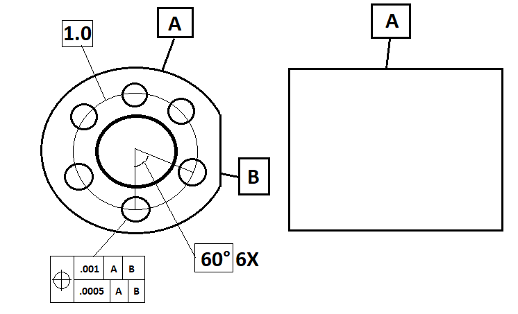
I am having trouble understanding composite tolerance, especially when it comes to a bolt hole pattern like this. I am wondering how you would dimension these true positions. Here's my idea using legacy dimensioning:
Level and translate to A, rotate to B, and report the position of 1 hole (any hole?...lets say the 12'O'Clock hole) and give it a .001 tolerance. Then, would I stay leveled to A&B, translate to the hole that I just reported on (12'O'Clock hole), and report the positions of the rest of the holes with a .0005 tolerance?
From my understanding the lower segments of composite only constrain rotational degrees of freedom. To check the lower segment create a feature set out of the holes, create a best fit alignment using the feature set allowing translation in the X and Y (assuming Z is looking at the holes) and set the best fit method to min/max. After the alignment redo the position of the holes. Technically you can also allow translation in the Z but you can't do a min/max best fit in 3D for some reason and least squares evaluation may not give you the best result possible