hexagon logo

Composite Tolerance


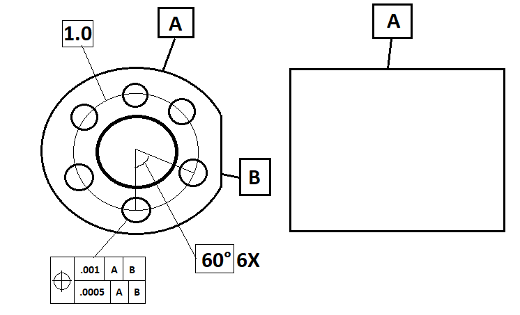
I am having trouble understanding composite tolerance, especially when it comes to a bolt hole pattern like this. I am wondering how you would dimension these true positions. Here's my idea using legacy dimensioning:

Level and translate to A, rotate to B, and report the position of 1 hole (any hole?...lets say the 12'O'Clock hole) and give it a .001 tolerance. Then, would I stay leveled to A&B, translate to the hole that I just reported on (12'O'Clock hole), and report the positions of the rest of the holes with a .0005 tolerance?​

Thanks so much...I prefer to use legacy...
Parents
  • Composite tolerances are used to give leeway to manufacturing.

    We could just have one segment with the tighter tolerance, but if the location and orientation relative to the mating part isn't so critical, we're tying manufacturing up to tighter tols than is actually necessary for the part to function thus adding cost to the design.

    By having a composite tolerance we can say, the mating part must assemble with a particular type of fit (think limits and fits here, we don't want a loose fit on the mating part), however once it's assembled we don't mind if it's orientation (angle) to the mating part isn't quite as good.

    Sorry for the fairly non-engineering scenario below but hopefully it will demonstrate the principal (I've used three segments to illustrate the options)


    Imagine we were designing a floating shelf (say 1000mm long), so we have a bracket which is a steel strip, with two rods protruding from it near each end, this will be fixed to the wall (using a level to ensure it's horizontal).

    The shelf is a thick plank of wood with two holes bored in it which locate on the rods.

    Let's call the back edge A, the top face B, and one end C.

    We need to ensure a decent fit on the rods, so the pitch, perpendicularity and diameter of the holes must be controlled fairly tightly. (This will be our lower segment)

    However, if the location of the holes to the top face of the shelf isn't perfect it's not a major issue, we might have a bit of a slope on the shelf (left to right) but 2mm over the length of the shelf it will have a negligible effect. (This will be our middle segment)

    Now the shelf is much thicker that the bracket and the holes aren't right at the end (so it will be hidden from view), so if the holes are 5mm up/down or left/right it's not an issue. (This is our top segment)

    We might have a three segment control frame like this:

    Ø5|A|B|C
    Ø2|A|B
    Ø0.5|A​
Reply
  • Composite tolerances are used to give leeway to manufacturing.

    We could just have one segment with the tighter tolerance, but if the location and orientation relative to the mating part isn't so critical, we're tying manufacturing up to tighter tols than is actually necessary for the part to function thus adding cost to the design.

    By having a composite tolerance we can say, the mating part must assemble with a particular type of fit (think limits and fits here, we don't want a loose fit on the mating part), however once it's assembled we don't mind if it's orientation (angle) to the mating part isn't quite as good.

    Sorry for the fairly non-engineering scenario below but hopefully it will demonstrate the principal (I've used three segments to illustrate the options)


    Imagine we were designing a floating shelf (say 1000mm long), so we have a bracket which is a steel strip, with two rods protruding from it near each end, this will be fixed to the wall (using a level to ensure it's horizontal).

    The shelf is a thick plank of wood with two holes bored in it which locate on the rods.

    Let's call the back edge A, the top face B, and one end C.

    We need to ensure a decent fit on the rods, so the pitch, perpendicularity and diameter of the holes must be controlled fairly tightly. (This will be our lower segment)

    However, if the location of the holes to the top face of the shelf isn't perfect it's not a major issue, we might have a bit of a slope on the shelf (left to right) but 2mm over the length of the shelf it will have a negligible effect. (This will be our middle segment)

    Now the shelf is much thicker that the bracket and the holes aren't right at the end (so it will be hidden from view), so if the holes are 5mm up/down or left/right it's not an issue. (This is our top segment)

    We might have a three segment control frame like this:

    Ø5|A|B|C
    Ø2|A|B
    Ø0.5|A​
Children
No Data