hexagon logo

Xact measure confusion

First, a little background: I'm using DMIS 2018 R1. The part is basically a sheet metal assembly of 2 layers of tin-plated copper that have been formed, with thin insulation between layers and on the outsides, and has been epoxied and pressed together, before being PEM'ed with M8 PEMS. I have 2 full datum structures on this part, the one on the top surface with a datum A being the flat surface, and datums B and C being 2 thru holes. The D,E,F datums on the lower surface are similar, and the E datum is dimensioned to the B, C datums on the top.


The odd thing about this part are the position callouts; there is no MMC on the hole dimensions themselves, but there is on BOTH datums, even though the positions for the datums themselves have no MMC callouts. That alone (I think) is improper, and I'm fairly certain that the dimensioning was probably done by a clueless summer intern. But, now
I have to deal with it.

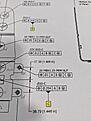
As an example, I'm showing the edit window for the position callout for the "22x" callout in the center of the other pic. All the unPEM'ed holes, whether datums or not, are Ø10mm +.3/-.1. Most of them run around 10.05mm, so my 'bonus tolerance' usually runs about .15 from any datum called out.

First question I have is this: Am I setting it up properly? Up in "Feature Control Frame Editor" window, is it correct that I enter the diameter of the datum at it's MMC value (being 9.9mm)? Or was I supposed to enter something else?

My second question (and the most important) is this: Why isn't the software calculating my position dimension actually using the bonus tolerance from the callout? When I calculate those 22 holes, no bonus tolerance is added, but at the end of the calculation, it does tell you what the bonus from the secondary and tertiary datums are, but it just doesn't use that info in the calculations. Am I missing something in my setup? Is there something in the "advanced" tab that can help me? Or, is this something that only an upgrade to a newer model of DMIS is going to fix?

Attached Files
Parents


  • First question I have is this: Am I setting it up properly? Up in "Feature Control Frame Editor" window, is it correct that I enter the diameter of the datum at it's MMC value (being 9.9mm)? Or was I supposed to enter something else?


    You shouldn't enter anything in the feature control frame itself for your datum feature MMB size. Ensure the nominal values and tolerances are correct in the advanced tab. Specifying a custom datum feature MMB size is usually not required and, in doing so, you could be overriding the actual MMB size calculated using combined effects of size and any applicable geometric tolerances.


    My second question (and the most important) is this: Why isn't the software calculating my position dimension actually using the bonus tolerance from the callout? When I calculate those 22 holes, no bonus tolerance is added, but at the end of the calculation, it does tell you what the bonus from the secondary and tertiary datums are, but it just doesn't use that info in the calculations. Am I missing something in my setup? Is there something in the "advanced" tab that can help me? Or, is this something that only an upgrade to a newer model of DMIS is going to fix?


    As said, a material modifier on a datum reference is not the same as a material modifier on a considered feature. (M)/(L) on datum references are MMB/LMB respectively, while (M)/(L) on considered feature references are MMC/LMC respectively. When the material modifier is on the considered feature(s), the size of the position tolerance zone can grow by the measured deviation from MMC/LMC size. When the material modifier is on the datum feature(s), only the MMB/LMB boundary is constraining the applicable degrees of freedom. As the datum feature deviates from MMB/LMB size, the applicable degrees of freedom are only partially constrained and the tolerance zone(s) are now free to float until the measured datum feature makes contact with its MMB/LMB.

Reply


  • First question I have is this: Am I setting it up properly? Up in "Feature Control Frame Editor" window, is it correct that I enter the diameter of the datum at it's MMC value (being 9.9mm)? Or was I supposed to enter something else?


    You shouldn't enter anything in the feature control frame itself for your datum feature MMB size. Ensure the nominal values and tolerances are correct in the advanced tab. Specifying a custom datum feature MMB size is usually not required and, in doing so, you could be overriding the actual MMB size calculated using combined effects of size and any applicable geometric tolerances.


    My second question (and the most important) is this: Why isn't the software calculating my position dimension actually using the bonus tolerance from the callout? When I calculate those 22 holes, no bonus tolerance is added, but at the end of the calculation, it does tell you what the bonus from the secondary and tertiary datums are, but it just doesn't use that info in the calculations. Am I missing something in my setup? Is there something in the "advanced" tab that can help me? Or, is this something that only an upgrade to a newer model of DMIS is going to fix?


    As said, a material modifier on a datum reference is not the same as a material modifier on a considered feature. (M)/(L) on datum references are MMB/LMB respectively, while (M)/(L) on considered feature references are MMC/LMC respectively. When the material modifier is on the considered feature(s), the size of the position tolerance zone can grow by the measured deviation from MMC/LMC size. When the material modifier is on the datum feature(s), only the MMB/LMB boundary is constraining the applicable degrees of freedom. As the datum feature deviates from MMB/LMB size, the applicable degrees of freedom are only partially constrained and the tolerance zone(s) are now free to float until the measured datum feature makes contact with its MMB/LMB.

Children
  • Example: Assume a primary datum plane (A) with normal vector along Z+ and a secondary datum cylinder (B) with axis along Z. Assume a second cylindrical hole is assigned a position tolerance with respect to [A|B(M)]. Datum A constrains two rotational degrees of freedom (DoF) and one translational DoF. Datum B constrains the remaining two translational DoF. Datum reference frame [A|B] is fully constrained in translation and free to rotate about datum axis B. Once datum B is referenced at MMB, the translational DoF that it constrains are partially released; the amount that they are released depend on how far away from its MMB datum feature B measures. The MMB is computed by considering the effects of size and applicable geometric tolerances with respect to datums referenced at a higher level of precedence (in this case, a perpendicularity tolerance on datum feature B with respect to datum A would increase its MMB size).

    The position of the hole to [A|B(M)] defines a tolerance zone that is perpendicular to datum A and basically located with respect to the MMB of datum B. As datum feature B deviates from its MMB, it can shift by an amount dependent on its magnitude of departure. This shift, or optimization, can be used to move the considered feature closer to its nominal location. The size of the tolerance zone does not change, the features can simply move through any unconstrained or partially constrained DoF.

    Mechanically, imagine a planar datum feature simulator used to simulate primary datum A and a pin used to simulate secondary datum B. If you machine the pin so it is at (MMC Size) - (Perpendicularity allowance on B with respect to A) and you place your part on the simulators such that datum feature A is on its simulator and datum feature B is around its simulator, you'll be able to not only rotate freely about the axis of datum B, but also translate within the plane of datum A as you change your point of contact with the simulator of datum B.