hexagon logo

Issue creating angled hole in cylider

Hi all,
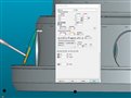
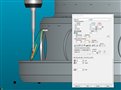
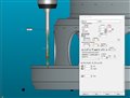
I have am currently struggling to create an auto circle/elipse in the side wall of a cylinder. I have a datum plane (flat face), and the cylinder is perpendicular to said face. However, the hole wall is angled at 20°. When using an autocircle/elipse to the CAD model, PCDMIS throws the circle to 20° to the face - normal to the wall of the hole. Could anybody please provide me with advice on how to get round this? I have attached a graphic which could perhaps explain this better.

Thanks in advance.​​

Attached Files
Parents
  • Update:
    As you are mentioning, I had rotated the datum on the example. I did initially try with my Z levelled to my datum face.

    The following attachment shows that the vectors still go normal to the hole surface. I the second attachment shows that when I alter my vetors to 1,0,0 - the hole is projected in X and Z.
    I understand i could work the nominals out, which i will do in the meantime, but surely PCDMIS can do this?

    Hope you can help.

    Attached Files
Reply
  • Update:
    As you are mentioning, I had rotated the datum on the example. I did initially try with my Z levelled to my datum face.

    The following attachment shows that the vectors still go normal to the hole surface. I the second attachment shows that when I alter my vetors to 1,0,0 - the hole is projected in X and Z.
    I understand i could work the nominals out, which i will do in the meantime, but surely PCDMIS can do this?

    Hope you can help.

    Attached Files
Children