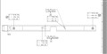
Good morning, attached is a pic I wanted to get some feedback on. I wanted to see what the best Alignment would be. Its a bent Part. Any Advice would be great. Thank you.
An orthogonal view would be useful here. What I'm seeing is a straight piece of square pipe, but viewed at an angle, with the holes machined into the part at that angle? So, what I see is the planar face A (facing towards you) is your A datum, right hole is your B datum, and the left hole is your C datum. Still, I have questions.
1) are the holes machined in perpendicular to the A datum, or perpendicular to the print view (that is, with datum A sloping)?
2) Which directions are X,Y and Z? By looking at the cartesian coordinates, it's hard to tell, but I suspect that x-axis is in the normal y direction.
If B and C are machined at an angle, you'll need to go into your feature edit window, and change the
i,j,k vectors to the correct direction.