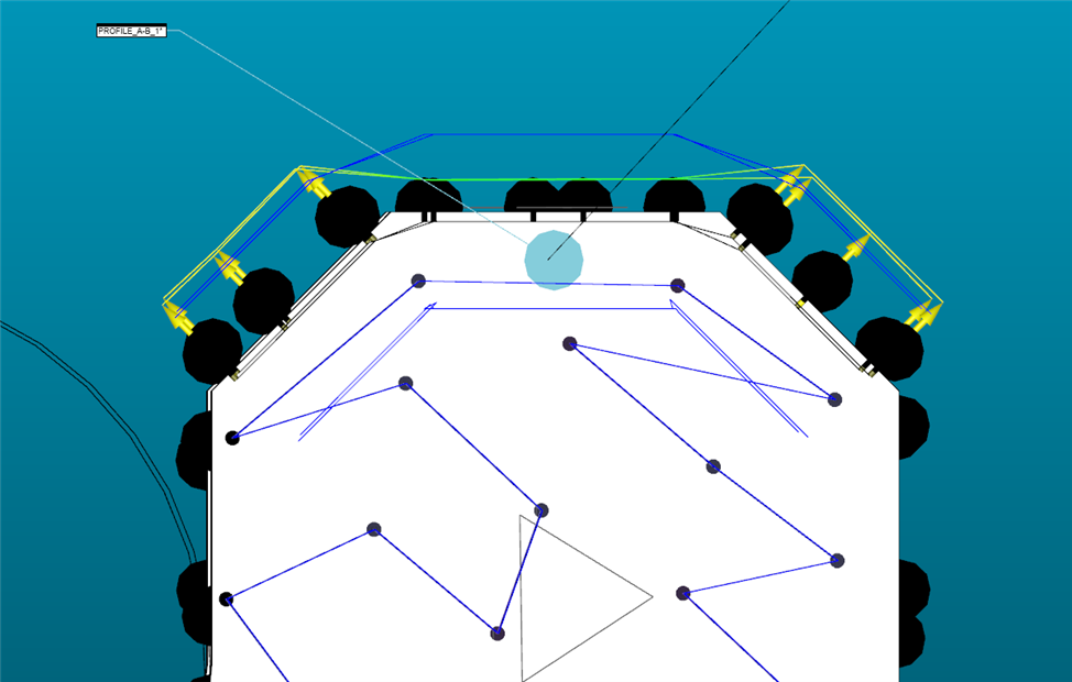
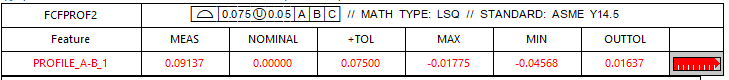
I have a part with a unilateral profile of a surface tolerance. The CAD graphic is showing that the part is out of tolerance externally. Mechanical measurements confirm that the part has more material than nominal. The geometric tolerance report label is showing the part out of tolerance
internally. Is there a reason for this discrepancy, or am I not reading the report properly?
If I get something like this, to be sure pc dmis check the profile right, I check the box T-value to see the distance between the actual points & the CAD points.
If I get something like this, to be sure pc dmis check the profile right, I check the box T-value to see the distance between the actual points & the CAD points.