I am revising an old program written sometime before 2012 and it's brought up some questions. First, why would one ever measure a plane and then construct an offset plane with an offset of zero? Second, if one did this, shouldn't dimensions referencing those planes give the same results? that is, the planes should be interchangeable? Instead this is what I'm seeing. I'm currently using version 2022.2 but this is translated from something earlier, probably last saved in 2017R1 in case that could possibly matter. The routine is saved as 2022.2 now though.
In theory, you could use an offset of 0, or a generic plane to "flatten" any flatness variation for the measured plane... but FRAK is only 3 hits (a 3pt plane will not capture any flatness, ever), so it makes absolutely zero sense.
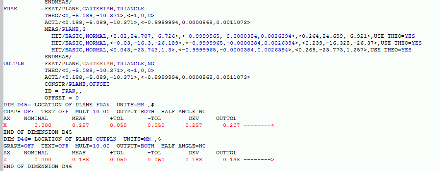
So I too am confused as to the following: 1 Why the two dims would produce different X axis values and 2 Why someone would do this intentionally in the routine
D45 x was from 3 hit points X value: average of 0.264 0.239 and 0.269
D46 x from the plane
Yes.
If offset plane OUTPLN is an offset of zero, and references FRAK, it should in theory have the same resultant dimensional value.
For D45 and D46 to have differing results, is alarming.
--You are 100% confident that you have executed this routine in its entirety to produce the results pictured (not CTL+e or CTL+u partial executions)?