I am revising an old program written sometime before 2012 and it's brought up some questions. First, why would one ever measure a plane and then construct an offset plane with an offset of zero? Second, if one did this, shouldn't dimensions referencing those planes give the same results? that is, the planes should be interchangeable? Instead this is what I'm seeing. I'm currently using version 2022.2 but this is translated from something earlier, probably last saved in 2017R1 in case that could possibly matter. The routine is saved as 2022.2 now though.
Perhaps it's poor phrasing to say it's not resolved, what I mean to say is I still don't understand it.
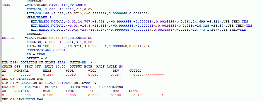
I mean, whenever the measured plane was measured, shouldn't creating a plane offset 0 have the same result? The key thing to notice is that in the first shared screenshot the x, y, z, i, j, and k measured values of each plane match, it is the dimensions (which again were inserted later, and therefore don't need updating) that don't match.
also I don't know how to insert a quote, hope this is understood even if it doesn't work. Here goes:
If you execute a routine partially, the resultant values of that execution are stored in the ACTL and MEAS results... which are then fed into dimensional outcomes. Every time you execute a routine entirely, all of the ACTL and MEAS results will change based on the ACTUAL and MEASURED values of that component you just measured.
But if I partially execute a routine, the same thing occurs, right? For the features I execute. All I executed in the first screenshot was the offset plane. I also created new zero offset planes and got the same dimension result for those as for OUTPLN. Which was the same result as the original routine had. Well, I mean there was no result for FRAK in the original, just for OUTPLN. I created a dim for FRAK and was concerned that it wasn't the same.
Incidentally the reason I created the dim for FRAK in the first place was that I didn't know why a zero offset plane would be created. I was thinking, "they're the same right?" so I did the dim and got concerned, especially when seeing the ACTL's in the feature.
Perhaps it's poor phrasing to say it's not resolved, what I mean to say is I still don't understand it.
I mean, whenever the measured plane was measured, shouldn't creating a plane offset 0 have the same result? The key thing to notice is that in the first shared screenshot the x, y, z, i, j, and k measured values of each plane match, it is the dimensions (which again were inserted later, and therefore don't need updating) that don't match.
also I don't know how to insert a quote, hope this is understood even if it doesn't work. Here goes:
If you execute a routine partially, the resultant values of that execution are stored in the ACTL and MEAS results... which are then fed into dimensional outcomes. Every time you execute a routine entirely, all of the ACTL and MEAS results will change based on the ACTUAL and MEASURED values of that component you just measured.
But if I partially execute a routine, the same thing occurs, right? For the features I execute. All I executed in the first screenshot was the offset plane. I also created new zero offset planes and got the same dimension result for those as for OUTPLN. Which was the same result as the original routine had. Well, I mean there was no result for FRAK in the original, just for OUTPLN. I created a dim for FRAK and was concerned that it wasn't the same.
Incidentally the reason I created the dim for FRAK in the first place was that I didn't know why a zero offset plane would be created. I was thinking, "they're the same right?" so I did the dim and got concerned, especially when seeing the ACTL's in the feature.
This is really fundamental.
PCDMIS records the last measured values in the ACTL and MEAS lines of code. Done. End of story.
--But to be more clear... Any partial execution of a measurement routine will produce & record updated ACTL and MEAS values.
IE: When you --partially execute-- a feature that is dependent on a feature that --wasn't partially executed--, you get weird deltas, like you snipped in your first post.
This occurs because the newly executed feature is relying on data that was recorded from a previous instance.... or it produces a null (THEO) reference output because that partial execution has no idea what the dependent feature is pointing to... that feature wasn't executed in that instance.
Resolution? There's a few.
1: execute routines offline before saving and setting to read only. All ACTL and MEAS values will match THEO.
2: DON'T partially execute code unless you are aware of what is stated above.
3: If you have a business need to partially execute routines on the regular, implement FLOW controls to automate the process (Input comments, Labels, IF/ END_IF, IF_GOTO, DO/WHILE, DO/UNTIL) etc.