hexagon logo

Positional measurements that I don't understand.

Hi Colleagues, I am currently working on one part which is a circle with three ears. It has positional measurements, which I had difficulty with. They are marked in red in the attached photos.
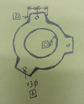
As far as I understand, if the reference point is the central circle, then the controlled elements should be controlled only along the PR, but I can not understand how to represent this in Pcdmis.
I hope you can give me some tips for this.
PS
I use 2014 version PCdmis, and xact.
PPS
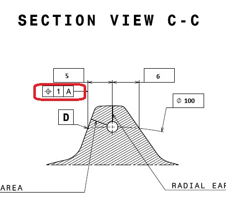
Datum D what is this??! Dia 100? But it's dat A in my opinion...Alien


Parents

  • I've seen this kind of gd&t callouts before & always wondered why engineers would make such a thing.
    On the left, what if you just create the point at D, report deviation coming from 5 & manually input into the T.P equation?
    On the right same idea but report deviation of x&y & do the same thing with T.P equation​


    At first I did just that, but it seemed to me that there was some kind of mistake in this and decided to ask here. Most likely, I will stop at this option, unless someone says that this is absolutely not acceptable.
  • I would improve this a bit in creating a bolt circle A, a line (if this is a straight surface per print not an arc) & intersect them where D is.
Reply Children
No Data