Let me start off by saying I just took the hexagon 201 course so I am trying to get more familiar with it here at work.
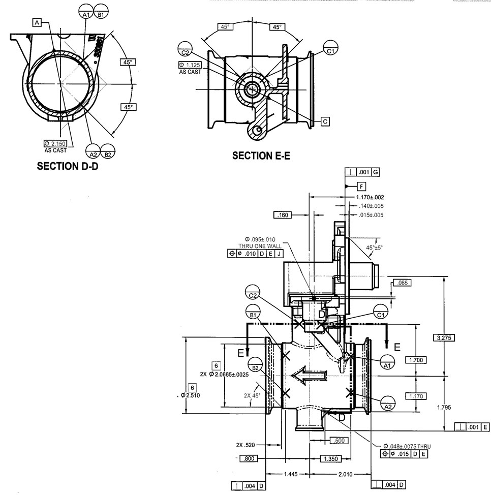
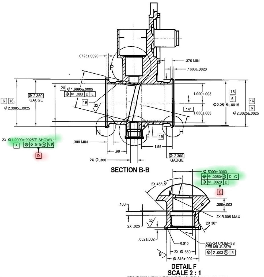
At my company we work with a lot of castings. They usually use datum targets to identify datum A, B, and C. I Have attached a part I am currently working on with the relevant information. As you can see it has two points for A, two for B and two for C. How would you use these points for an iterative alignment? As far as I have read through the forums I've only seen examples with the 3-2-1 method. When I try using 2 points to level it just give me a message saying I need 3 points. I have seen on the pcdmis website a table saying I could use 3 circles in DCC mode but not much more information on that.
What is the reason for the Datum Scheme?. it seems to align just one side of the part, which seems strange. I think you are going to end up with a best fit alignment if you use these datum points,
in the iterative alignment level with A1, A2, B1,B2, rotate with C1, C2 or B1, A1, origin on C1 or C2.
I'm not seeing ABC used in the FCF you have shown. Do any actually use them? It could have been drawn by someone who doesn't understand GD&T (there are about 99 out of 100 that don't).
Maybe do the alignment as a normal alignment, rather than iterative.
Looks like A1 and A2 make an origin line.
B1 and B2 look to be an origin line. Probably use this as the rotation.
C1 and C2 look to be an origin line.
Looks like somebody has an unorthodox understanding of casting datums.
As Matthew said, the ABC feature control frame should be used to 'hand off' the datum scheme from the casting to the first in-process cuts and their new datum scheme.
The only place in the entire print they are referenced are true position for the two main machined datum surfaces. My guess is that it is just to make sure the machined surfaces are centered with the casting?
A-B basically means that they (the 2 A's and the 2 B's) make a common datum, as in, use those 4 as 'level', which will work in an iterative alignment, as long as you come up with the other requirements.
IMHO.. whoever drew this did not understand GD&T. I agree the A's & B's could level but the C's would attempt to constrain one of the DOF from A-B. Get clarification of intent from engineering!
Well I'll be honest my company has been running these parts for years and years and have never checked those call outs using the target points. But when I took the class is where I first learned what those little bubbles were. So I figured there might be a way to check them the "right" way. The thing is a lot of our casting parts have this dual target point set up. I just wish I knew what to do with the information