hexagon logo

Error: Compound or pattern datum must be perpendicular to datum plane.

I recently was tasked with measuring a part bent at an angle with a pattern of holes on both surfaces of the bend. The bottom plane is Datum A, the bottom pattern of holes is Datum B. There is a profile locating all of the edges on the bottom plane to Datums A|B. The top bent plane is Datum C and this angled bend is controlled with flatness and Profile to Datums A|B. Finally, on the Datum C plane, there is a set of two holes, Datum D. These 2 holes have a position callout to Datums C|B as well as just to Datum C. Everything works fine in PC-DMIS until I try and find the position of these top 2 holes. Finding their position to Datum C works just fine (as it's controlling their relation to each other and perpendicularity to the plane they're on), but when trying to calculate their position to Datums C|B I get the following error: "Compound or pattern datum must be perpendicular to datum plane."

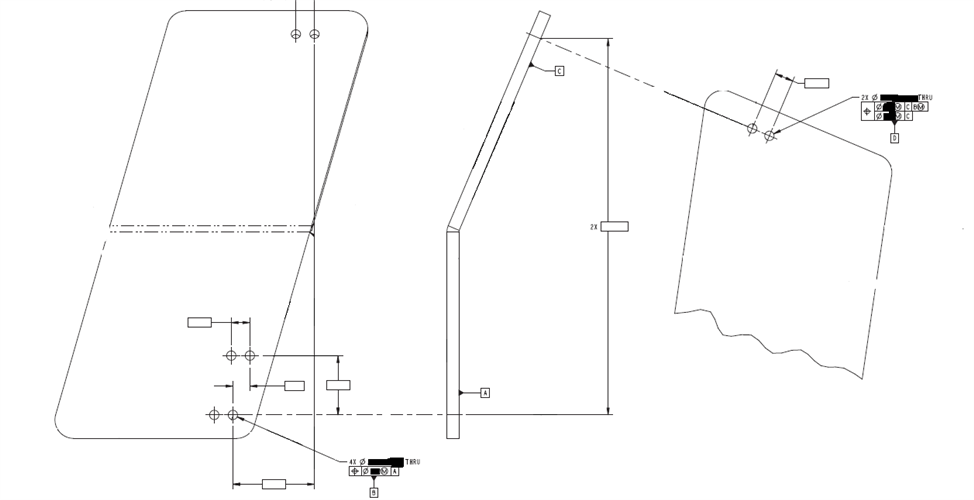
Attached is a rough sketch of the print (everything, but hole positions and Basic dimensions were removed). I certainly get the design intention, and the GD&T kind of makes sense as well. The design intends for the top holes on Datum C to be within XXX position of the Datum B hole pattern (located on Datum A)

Am I doing something wrong? Is the GD&T wrong? If it is wrong, why is it wrong and how can it be corrected? I talked with the design engineer behind this part and they think that they GD&T is correct, so I'd definitely need a strong argument to make any sort of print change.

Sorry for the rambling, I hope it all makes sense!
Parents
  • I think I get the design intent, but I also see why the software has an issue with it.

    If Dat C is controlled by profile to A|B then that ensures the bent plane is in the right location.

    If the part assembles on A and B, then the mating part (mounted to the holes in Dat C) needs to be controlled to that location then calling it back to A|B would make sense.

    I'd argue perhaps that the holes in datum C should also be controlled to A|B - perhaps with a separate perp call out to C.

    Alternatively would those holes called to C|A|B also work.
Reply
  • I think I get the design intent, but I also see why the software has an issue with it.

    If Dat C is controlled by profile to A|B then that ensures the bent plane is in the right location.

    If the part assembles on A and B, then the mating part (mounted to the holes in Dat C) needs to be controlled to that location then calling it back to A|B would make sense.

    I'd argue perhaps that the holes in datum C should also be controlled to A|B - perhaps with a separate perp call out to C.

    Alternatively would those holes called to C|A|B also work.
Children
No Data