What exactly is this implying? I've seen a profile composite to ABC and A, ABC and AB, but not A and A. PCDMIS seems to be calculating it but I can't make sense of it.
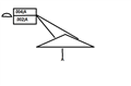
I know this is a napkin sketch, but I'm assuming this is supposed to portray a composite profile.
Composite dimensions are checked to the datums *rotationally* while the upper segment is checked *rotationally and translationally*.
So in this case, the upper segment wants to ensure that if you leveled and origined to Datum A, the entire surface profile is within tolerance zone normal to the surface.
The lower segment want to ensure that if you leveled to Datum A, but origined to the feature itself, the entire surface profile is within the tolerance zone normal to the surface. This is essentially a form only profile tolerance with one extra rotational constraint (Datum A).
*Thought experiment* Imagine you have the same call-out you have on your drawing, but the profile surface is a parallel plane in relation to Datum A. For the upper segment the profile call-out would be checking both the distance of that surface to Datum A, plus parallelism to Datum A and flatness all at the same time.
The lower segment would only be checking parallelism to Datum A and flatness. When I said before that this is form only callout with one extra constraint, form only would be flatness only in this example.
So, if I were to a dimension this in legacy in PC DMIS, (assuming this is a 3D triangle) I would...
Top segment- Level and origin to Datum A, create a best fit full 2D (both rotation and translations) about the axis of the level using the features used to create the profile surface. Then dimension profile.
Lower segment- Level to Datum A, create a best fit alignment that locks rotation about the axis of the level and also best fits all 3 translational axis to the features used to create the profile surface. Then dimension profile.
*EDIT* Composites can be confusing, but the ASME standard has some pretty nice visual representations of multiple segment composites. Your drawing could technically have a 3rd composite segment using no Datums (form only) and it would still be proper.