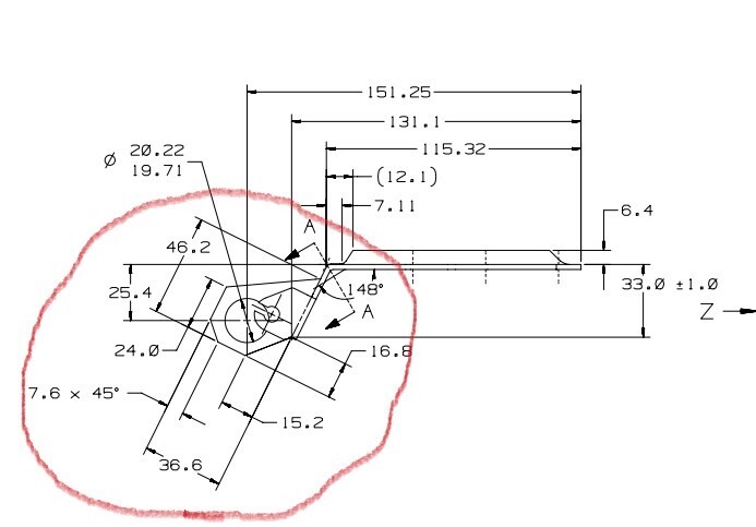
Usually there would be an angle called out on the print to rotate too. Otherwise if you have a CAD model, you can get it from there. But with all them linears being on there, it really should have been on the print.
If you take the slanted flange with the 33.0 distance. that gives you a distance for one leg of a right triangle. the next leg is 131.1 - 115.32= 15.78. Plug that into a calculator and you get an angle of 64.444 degrees.
Take a plane or a line on the flat surface you're taking your distance from and rotate to that. Looks like there's three different rotations you'll need to get all the dimensions, but all of them looks like they're attached to a flat surface you can rotate to.
When I execute my alignment the trihedron stays where it is. I have turned off the "force part alignment in car body" option, but the axis is staying in the same spot.
If you place your cursor above the alignment and then below, the trihedron isn't shifting based on your new selections?
Could you share some or all of the code so we can see if there is something awry?
After reading the helpfile, that appears to be why your trihedron does not shift.
Do you need to use the 'Force Part Alignment in Car Body' or did you select it just because? Maybe uncheck that box and attempt those evaluations. Not sure if it would require any additional effort as I don't use that selection myself.
those dims can be done by line-point (point is from the intersection of the two surfaces) distance perp to the line feature that is used. No need to rotate....