When a datum feature is referenced at a material condition other than RMB (i.e. MMB or LMB), the datum feature simulator is a fixed size. As the datum feature departs from the fixed size, it is allowed to move around/within the datum feature simulator by an amount that corresponds to the amount of departure. The movement that can occur (datum shift) is movement through any degrees of freedom that the datum feature constrains. For example, a cylinder will constrain two degrees of rotation and two degrees of translation (if no other datum feature references of higher precedence constrain those particular DOF first). Once the cylinder is referenced at a condition other than RMB, the related tolerance zones can be optimized in rotation and translation.
The rules for determining the size of the MMB or LMB are considered more complex than introductory GD&T, but they are written in Y14.5 and I'd encourage you to go read through the standard to determine the rules.
You can get the report to omit datum shift information by removing material modifiers on your datum feature references. You can also modify the rule tree of the report template, but I wouldn't advise it. Lastly, you can update to a version of PC-DMIS after, or including, 2020 R2. The GD&T library was overhauled, the XactMeasure command was replaced with the Geometric Tolerance command, and all information on datum shift was removed from the report. This third option would be my suggestion as the newer command is much more stable than XactMeasure was with non-standard GD&T.
It's often best to not use datum shifts in PC-DMIS.
2 reasons:
1) PC-DMIS actually deducts the measured position from feature actuals (often reporting perfect measured position), rather than simply adding to dimension bonus. This usually makes the data useless to customers.
2) Except in very limited circumstances, PC-DMIS does not calculate simultaneous evaluation correctly (no CMM software does, without extremely advanced programming).
Now, if you have one of the extremely limited conditions where PC-DMIS doesn't calculate this completely wrong, you can report positions both with, and without the datum shift. Once to tell the customer where the features lie, and once to inform the inspector if that's in, or out of tolerance.
I'm with
JacobCheverie on this one. Unless you can provide concrete evidence to back up your assertions, please refrain from stating that PC-DMIS is calculating datum shift incorrectly. This is not the first time you have made such unfounded assertions which is why I am stepping in now to prevent the spread of mis-information.
PC-DMIS calculates datum shift in accordance with ASME Y14.5 (see extract from Y14.5 - 2009 below - a similar statement appears in Y14.5 - 2018 section 7.11.11).
4.11.9 Datum Feature Shift/Displacement
MMB or LMB modifiers applied to the datum feature
reference will allow the datum feature to shift/displace
from the boundary established by the datum feature simulator
in an amount that is equal to the difference between
the applicable (unrelated or related) actual mating envelope
for MMB, actual minimum material envelope for
LMB, or surface of the feature and the datum feature
simulator. The datum reference frame is established from
the datum feature simulator and not the datum features.
See Fig. 4-17 for LMB, Figs. 4-18 and 4-24, datum feature
B in Fig. 4-26 for MMB, and Fig. 4-30, illustration (b) for
the surface. The datum feature shift/displacement shall
always be limited or constrained by the datum feature
simulator. If the datum feature simulator geometry is
such that it does not fully limit or constrain the feature
such as rotating away from the datum feature simulator
beyond the established boundary limits, as shown in
Fig. 4-31, illustration (c), then the feature must remain
in contact with the datum feature simulator, and datum
shift or displacement is not allowed. See para. 4.16.7 and
datum feature A in Fig. 4-28.
NOWHERE within the standard does it say to "simply add" the MMB to the feature bonus as this would be wrong, resulting in the acceptance of bad parts. Take the example below, showing the position of two holes relative to a central cylinder at MMB. It shows the holes out of position and would result in zero datum shift because they are off location in opposite directions. If we were to simply add the bonus from datum C to the positional tolerance it would result in the holes being incorrectly accepted and the part would not assemble.
With legacy position, you are able to control whether datum shift is applied or not and it is possible to add the bonus from the datums to the positional tolerance. However, the help is very clear in pointing out that this functionality was added at a customer's request, purely to allow them to provide process adjustment information and is not compliant with ASME Y14.5
Agreed. Probably engineers like datum shift & GD&T gimmicks like this because in theory it gives them more room to play & write out engineering deviation if they need to. But as usual not pay attention that measuring their ideas is a big headache. Same goes to composite FCFs. The machinist doesn't care about those GD&T gimmicks either when creating toolpaths using a model in Mastercam. The features should be in the right location regardless of datum shift or not.
NOWHERE within the standard does it say to "simply add" the MMB to the feature bonus as this would be wrong, resulting in the acceptance of bad parts.
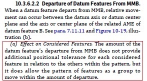
In fact, see the following from Y14.5-2018. The standard specifically disallows the addition of the amount of the departure from the MMB to the size of the tolerance zone.
That information is completely useless to any machinist. Reported basics should still reflect reality.
I did report circumstances where simultaneous evaluation is calculated incorrectly (usually where the features of interest are concentric with datum using the shift.
In the future, I will not report any more PC-DMIS bugs.
Just FYI,
JacobCheverieneil.challinor In response, "Do you have any concrete examples in which, using the new Geometric Tolerance, PC-DMIS does not calculate simultaneous evaluations correctly?"
Yes, actually... PC-DMIS does not calculate simultaneously evaluated composite TP's correctly, as one example.
At least in Xact, you would clearly see multiple DOF's within each FCF, knowing the composite is not being SIMTOL... In GeoTol,
you're completely mislead with the removal of the DOF segment, leaving multiple FCF's labeled, "SIMTOL" while in-fact there being evaluated
independently. No warning or error message either...