The Things121 The ASME Y14.5 standard shows that lower segments of a composite FCF are not, by default, evaluated simultaneously. Do you have a concrete example in which the math that PC-DMIS is performing is incorrect?
As far as the removal of the datum shift label, there is a post on the Idea Center to bring that information back. I believe Hexagon removed it because it was more confusing than helpful in a general sense, but I'm sure they're open to giving us that information again if enough people ask for it.
I am with @
Kai Kendall on this one. It is probably a better idea to not use MMB from the datum features in general. I don't think he is saying your math is wrong but more that you need to be very careful when using this or you will get wrong results.
When you have datum shifts (which is a modification of the alignment system to suite one or more Geotol dimensions) you end up with two (or more) distinctly different alignment systems. The problem is you don't see the impact of this change in anything you cannot tie together using the Simultaneous Evaluation command. If you had a random vector point measured somewhere you would not see its value change following the datum shift for example. If you simply ask for the XY location of your datum features you won't see the change in location as a result of the datum shift.
A classic example is when you report a series of position dimensions where each shows no deviation in the result. You have the original alignment system of the part and one unique alignment for each separate position dimension.
There should only be one alignment system. If it is modified by a datum shift you should see this effect on everything. The Simultaneous Evaluation command in PC-DMIS tries to address this problem but it doesn't quite go far enough. Unless you are extremely careful your report will show results from the two or more alignment systems that exist.
I have used software where the impact of a datum shift suddenly changes everything on the report. At first I thought it was a bug but in retrospect I understand what they did and why.
JacobCheverie "By default" this is mere word play in Y14.5. I'm confused by your statement, are you saying this isn't allowed? If so, see the
bold, below.
Y14.5 2009 - 4.19: "A simultaneous requirement is where two or more geometric tolerances apply as a single pattern or part requirement. A simultaneous requirement applies to position and profile tolerances that are located by basic dimensions, related to common datum features referenced in the same order of precedence at the same boundary conditions. In a simultaneous requirement there is no translation or rotation between the datum reference frames of the included geometric tolerances, thus creating a single pattern. Figures 4-39 and 4-40 show examples of simultaneous requirements. If such interrelationship is not required, a notation such as SEP REQT is placed adjacent to each applicable feature control frame. See Figs. 4-41 and 7-54 and para. 7.5.4.2.
This principle does not apply to the lower segments of composite feature control frames. See para. 7.5.4.2.
If a simultaneous requirement is desired for the lower segments of two or more composite feature control frames, a notation such as SIM REQT shall be placed adjacent to each applicable lower segment of the feature control frames.
This is 100% a valid call-out - multiple OEM's (Boeing, Sikorsky, SAAB, etc..) view and engineer in such fashion. If you think about it, you have a traditional
fully constrained upper segment (3 Datum Planes/ABC), and a composite (1 Plane/ A) SIMTOL does absolutely nothing for the upper segment, the under constrained composite is what you'll want to be simultaneously evaluated...
Which, PC-DMIS does not calculate - it's worse, it
100% misleads you into believing it actually is being evaluated simultaneously, when it's not supported, even though this is a valid call-out to many.
"Do you have a concrete example in which the math that PC-DMIS is performing is incorrect?" So, I would say the "math" isn't being preformed correctly - as it's not even being done lol. With all the redundant "warning" messages PC-DMIS has,
there's zero excuse for not having, "SIMTOL error, composite tolerance cannot be simultaneously evaluated"
I was completely burned by this. There is also other, well-respected Senior members of this form that could also be burn like I was, referencing my post above again.
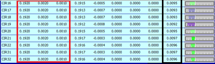
"Do you have a concrete example in which the math that PC-DMIS is performing is incorrect?" Outside of, composite not being evaluated simultaneously.... Look at the screenshot below of a SIMTOL Single Segment FCF's for groups of holes. Notice how PC-DMIS calculates MMC bonus of
.010" (black box) when I have a
+.002 -.001 tolerance (red box)...
See JacobCheverie's response below. Under ASME Y14.5, simultaneous evaluations do not apply to the lower segments of composite position or profile tolerances.
Thanks Jacob. As for the datum shift information, you are correct, it was removed because the majority of users did not want it on their reports. We are currently discussing how to make the datum shift information available again to those who want it. We can not simply "turn it back on" because the geometric tolerance commands are completely different to the older, XactMeasure functionality they replaced, we would need to re-write supporting code from scratch and want to be sure we get the design right.
The ASME Y14.5 passage you quoted states that simultaneous evaluations do not apply to lower segments of composite feature control frames unless specifically invoked:
This principle does not apply to the lower segments of composite feature control frames. See para. 7.5.4.2. If a simultaneous requirement is desired for the lower segments of two or more composite feature control frames, a notation such as SIM REQT shall be placed adjacent to each applicable lower segment of the feature control frames.
That is why PC-DMIS does not support simultaneous evaluations for lower segments of composite FCFs.
Your screenshot looks like it comes from an XactMeasure report. I am not claiming that XactMeasure was 100% accurate and error free as I was not involved with PC-DMIS when XactMeasure was introduced and have no way of fixing any errors that may come to light (the code has been deprecated). I am solely focusing on the new Geometric Tolerance commands which completely replaced XactMeasure for PC-DMIS 2020 R2 onwards and for which I have been heavily involved. To the best of my knowledge, there are no problems with the geometric tolerance math and it performs simultaneous evaluations correctly. If you have evidence to the contrary then I would be happy to review it with you over a private call and, if validated will of course instruct my team to provide a fix as soon as humanly possible.
I have actually forced correct simultaneous evaluation in Quindos (like where C gets a bonus for certain things, and both B and C on others), but it gets EXTREMELY complex, even with only 2 or 3 features of interest.
Am in the process of developing an improved (simpler) method in Quindos that should also work in PC-DMIS. Give me about 3 years.
@
Kai Kendall. It would be interesting to know your approach to solving this problem in Quindos. The only approach I know of is to take all measured data and try to fit it against a simulated 'perfect' part. The constraints is not just the datum features but all features and varying tolerances which is what makes it insanely difficult. This is not a new problem and if a good solution existed everyone would be using it by now.
One comment that someone mentioned to me long ago was that if you only have a few features you have some 'wiggle' but this disappears as the number of features increase. Picture a mating part with three holes/pins where you can shift it around a bit then compare it to a similar part with 100 holes/pins; the second version won't wiggle nearly as much as the fist version. They did a study on this and decided that simply ignoring the datum bonus was the best, practical, option as the results were pretty much the same anyway when you have a lot of features.
If you are doing this the goal should not be to make features 'perfect' either. Every datum shift that improves one item makes something else worse by the same amount. Tolerances come into play particularly in this case.
Datum shift is very helpful, it tells you if the calculation has been performed as the DRF states and you should eyeball that result for verification that it indeed is correct.
Now, Hexagon has removed this information in the later versions because some customers don't understand them - which is really, really sad.
I liked it because it would show you what degrees of freedom had been best fitted and what degrees had been fixed. You could then verify that your creation of the datum features type and what was happening in the GD&T in the feature control frames was theoretically correct. Agree, kind of sad that you can't see that information anymore Just numbers in the result.