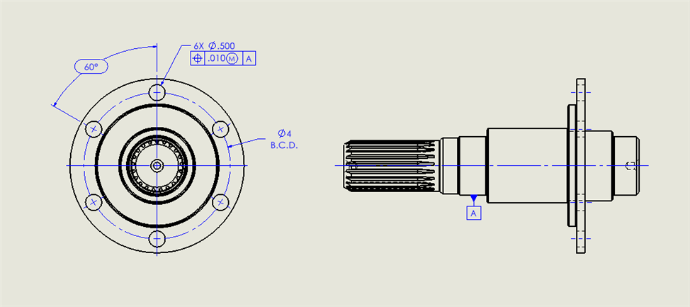
I don't know what this true position on the hole is constraining. Bolt circle diameter or orientation of the hole maybe? Trying to determine if I need to measure the hole as a cylinder. Appreciate the help.
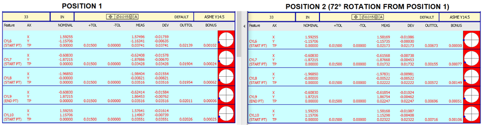
I have a similar part and can tell I'm doing something wrong. This part has 5 holes in the flange and I got all 5. I noticed the x,y deviation is always in the same direction on my parts. So I rotated one part and measured again and the direction stayed the same. The datum A used is a cylinder measured in dcc with 2 levels. Getting different values so I know something aint right but perplexed as to why the true position is always off in the same direction.
I have a similar part and can tell I'm doing something wrong. This part has 5 holes in the flange and I got all 5. I noticed the x,y deviation is always in the same direction on my parts. So I rotated one part and measured again and the direction stayed the same. The datum A used is a cylinder measured in dcc with 2 levels. Getting different values so I know something aint right but perplexed as to why the true position is always off in the same direction.
I did not read the whole thread, but skimmed. I think you want to remove the diameter symbol just before the dimension tolerance. Note that your print does not have that.
Using a cylinder as a primary datum is fine provided it is of sufficient length. Notice the distance between datum cylinder A and the flange is longer than the length of the cylinder. This can lead to projection errors.
Finding the cause can be difficult sometimes. I always start with my probes. Whenever possible use one probe for your alignment and critical features. You may want to check the perpendicularity of the cylinder to the flange plane.