I don't know what this true position on the hole is constraining. Bolt circle diameter or orientation of the hole maybe? Trying to determine if I need to measure the hole as a cylinder. Appreciate the help.
It's essentially the hole pattern to itself.
Probably will have to a manual alignment using two of the bolt holes to offset before going to DCC.
Create a cylinder on Datum A, then level and set the origin on it.
Measure the bolt hole circles and do a 2D best fit rotary alignment. (Terminology may not be correct.)
Then report the position of the bolt hole circles.
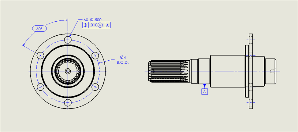
Without seeing the rest of the print, it may need to be timed to something (i.e. the spline), or it will say something to the effect of "timing of features to each other is not important". The 60° basic dimension, and the 4" BCD (I'm under the assumption that was also basic?), need to be held to [A].
It's essentially the hole pattern to itself. Probably will have to a manual alignment using two of the bolt holes to offset before going to DCC. Create a cylinder on Datum A, then level and set the origin on it. Measure the bolt hole circles and do a 2D best fit rotary alignment. (Terminology may not be correct.) Then report the position of the bolt hole circles.
I can follow those instructions, but I don't quite understand how the position of the hole is being reported with respect to the datum. Since were measuring the hole as a circle I know it cant be the orientation of the hole. Is it basically the concentricity of the bolt pattern diameter to the datum cylinder?
Timing of the splines is random. How would the 60° dimension be held to A? I can see how the 4" BCD would be held to A. Just to note those dimensions have a higher precision and tolerance on the actual print, I just simplified them and changed the numbers to avoid the chance of getting in trouble.
Imagine the part was a plate with a random group of holes and the same position callout. Datum A is one side of the plate. The callout is saying that we care about the location of the holes to each other but we don't care about how they relate to the edges of the plate.
This part is similar. The relationship of the holes to each other is what's important. The cylindrical Datum A is the only thing orienting and anchoring the holes. The holes have to be parallel to Datum A within .010 (plus bonus) while also being with a 0.010 diameter (plus bonus) to each other.
The 60 degrees and 4.0 diameter are indicating the ideal location of the holes in the bolt circle. The designer could have just as easily used XY dimensions to show the ideal hole locations without changing the meaning of the Position requirement.
EXCEPT that the holes NEED to be in relationship to the 'shank' that is the "A" datum. So you level & origin 2 axis to that shank (4 DOF) and the holes can then (per that callout) be 'anywhere' around that 'flange', but they MUST be in relationship to each other (WITH the 'shank' being at zero in 2 axis) but the rotation about the shank can be 'anything'.
And technically, there is no such thing as a 'circle', only cylinders, so, yes, measure as cylinders as both ends must be within the CYLINDRICAL tolerance zone called out