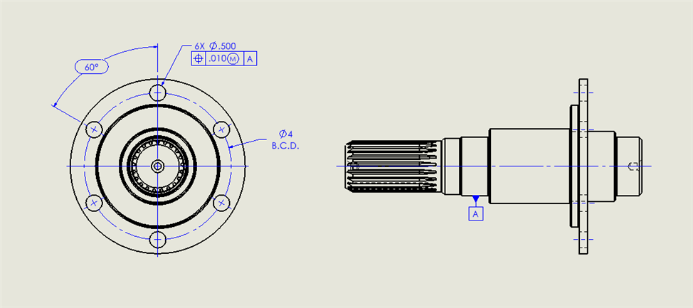
I don't know what this true position on the hole is constraining. Bolt circle diameter or orientation of the hole maybe? Trying to determine if I need to measure the hole as a cylinder. Appreciate the help.
It's essentially the hole pattern to itself.
Probably will have to a manual alignment using two of the bolt holes to offset before going to DCC.
Create a cylinder on Datum A, then level and set the origin on it.
Measure the bolt hole circles and do a 2D best fit rotary alignment. (Terminology may not be correct.)
Then report the position of the bolt hole circles.
Same here. I would though remind engineers to make one hole preferably the top (where the dim line is point to) as a datum hole or write on the print to clock to that hole. A CNC machinist always starts to drill 1st hole somewhere. Engineers should designate that specific hole as tertiary datum hole. You need to clock the cmm alignment to something to make the machine find rest of holes.
If a clocking hole is called out, then you are actually losing tolerance. It forces the hole pattern into a specific orientation. You lose the bonus tolerance from the clocking hole. On the other hand, if all of the bolt holes are used for orientation, then the alignment will shift as needed. Using all the bolt holes for orientation is how the part will mate in the assembly. The clocking hole method does not represent assembly conditions. As far as writing the CMM program, then a temporary alignment using a clocking hole is a good idea. But it needs to be followed up with a 2D best fit rotary alignment so that all of the available tolerance is available.
Except that the machinist who programs the toolpath will always start with drilling one hole preferably the one along center axes & move the tool at those angle intervals along the radius (dia/2) from that hole. So that one automatically hole becomes rotation tertiary datum.
The machinist can do whatever they want as long as the part meets print requirements when they are done with it. Our job is to measure the part, using the full amount of tolerance available.
And our job is to inspect part like it was manufactured. Too many times a designer designs the component one way, it's made a another way & it's checked yet another way. No wonder all the bickering going one back & forth.
MattR: Gonna have to disagree with you. As Quality Control, our primary job is to ensure that the part meets requirements. Manufacturing's job is to ensure that the part is made to requirements. Design's job is to ensure that a functional, manufacturable part is conceived and communicated. This doesn't mean that we won't work with manufacturing and design to ensure a good product. At the end of the day though, all of our jobs is to ensure that the best possible product is produced and delivered to the customer in a timely manner. Final inspection of a part like it was manufactured is asking for trouble. Parts can often easily meet manufacturing's plan but don't fully meet design's requirements. Thats not to say that QC won't help execute manufacturing's plan but ultimately our responsibility is to ensure print requirements are met.
Disagreements are fine. Fundamental problem is the disconnect between design & mfg. In our place our team has been inspecting to the mfg for years because more often than not our designers don't have full understanding of machining vagaries & how GD&T plays its role in mfg & assembly.
GD&T is a design standard, not a manufacturing or inspection standard. I do agree that often inspection and manufacturing often have a better understanding of the subject. However, doing an end run around design is often the cause of the bickering. Manufacturing, quality and design have to have a common understanding of the requirements and how they are communicated. It will take a lot of hard work on all parties part to get there.