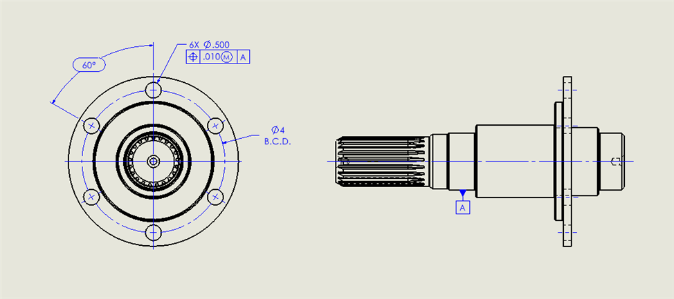
I don't know what this true position on the hole is constraining. Bolt circle diameter or orientation of the hole maybe? Trying to determine if I need to measure the hole as a cylinder. Appreciate the help.
It's essentially the hole pattern to itself.
Probably will have to a manual alignment using two of the bolt holes to offset before going to DCC.
Create a cylinder on Datum A, then level and set the origin on it.
Measure the bolt hole circles and do a 2D best fit rotary alignment. (Terminology may not be correct.)
Then report the position of the bolt hole circles.
GD&T is a design standard, not a manufacturing or inspection standard. I do agree that often inspection and manufacturing often have a better understanding of the subject. However, doing an end run around design is often the cause of the bickering. Manufacturing, quality and design have to have a common understanding of the requirements and how they are communicated. It will take a lot of hard work on all parties part to get there.
GD&T is a design standard, not a manufacturing or inspection standard. I do agree that often inspection and manufacturing often have a better understanding of the subject. However, doing an end run around design is often the cause of the bickering. Manufacturing, quality and design have to have a common understanding of the requirements and how they are communicated. It will take a lot of hard work on all parties part to get there.