
Bear with me, I´m trying to make myself clear.
I have a part thats looks like this.
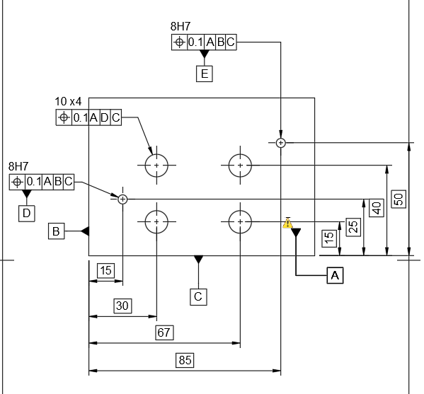
The 8H7-holes are clear to me. I can report the positions with A,B C. No problem.
No comes the part that is hard for me to understand, since I don´t know how PC-Dmis solves that.
My alignment is in the left bottom corner.
Then I do the datums D, E.
Then I report the positions of the Ø10 holes.
But here is my problem:
They refer to the datums D and E but the theoretical dimensions refer to B and C.
When I choose "DISPLAY_COORDS=DRF" it basically sets the aligment to A, D, E and reports refered to that alignment.
When I chhoose "DISPLAY_COORDS=CURRENT ALIGNMENT" the reported values are based on the theoretical dimensions shown on the drawing.
The deviation of both positions are the same.
But when I report the Ø10 holes to B and C the deviations are different.
This is the point that I don´t understand how PC-Dmis solves that.
I hope I made myself clear.
