hexagon logo

Combining multiple Cones into one cone

​I've seen different variations of this question asked but I can't seem to find my exact predicament.​
I have a small part that I'm inspecting and the only way I can probe it is to go around the part at 4 different angles using cones.

What I'm doing is, pretend that these cones are 90° included. I'm setting my probe angle to A45B0, probing the cones, then A45B90, probing the cones, A45B-90, probing the cones, then finally A45B180 and probing the final cones. After this, I create a constructed set using all the cones and dimension them with a profile tolerance(.002'). Now from what I can see, our parts look good, in terms of angles and position, but for whatever reason the profile tolerance is out of tolerance.

Is this the best method to use to inspect these features?


Is there a way to combine these cones in order to use the measured points into a larger cone?

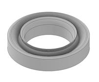
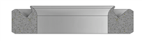
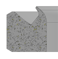
Example of the part (Not the actual part):

  • Try using single points (autovector points) instead. I used to have problems with auto/measured cones for some reason switched to just points & constructed cones or sets from that. Maybe that was some odd version of pc dmis but I can no longer recall. But I went with points from that point on regardless of what version I work with. Verify your alignment too because stuff like profile and/or position do get affected by crappy alignments or dirty pieces.
  • So your angles could have more +/- tolerance independently than the profile tolerance condones? Your position would only be the centroid of the feature(s) compared to the datum structure which can pass too depending on the applied tolerance. It seems your detail points are drifting outside your profile tolerance. You can review if it is something consistent by reporting with T-Value for each point instead of attempting to evaluate the set as a whole, then you know where to focus with any correction(s).
  • Older version of PcDmis:
    Construct a cone BFRE.
    Select the four pieces and hope the math works since it is using four centroids.
    After each one, add .hits[1..conX.numhits] where conX is the name of the feature you are typing that after.

    IF the math doesn't work, select things until it does work.
    Then add the .hits statement above and delete the features that should not have been included in the first place but you needed to get successful math.

    Newer version of PcDmis:
    Construct BFRE
    select the cones in the window
    In the graphics window click the points individually and it will use the points for you.

    You are rotating the head, so you want to recomp (the RE part of BFRE).

    I've done this with speherical bearing races and dovetail grooves (like you're doing) without issue in the past.

    You want to have points that have a common Z, so you have circles of points.
    If you have a newer version where you can click the points in the graphic window, click them in circles instead of clicking them by cone segment.
  • So I think this is giving me the closest to the true result I was expecting. Thank you for your input!
  • How would I use T-Values to understand whats going on?
  • , T-values are localized profile evaluations for individual points. It can help you to see where the stock condition is causing your profile failure. Some people utilize graphs too when looking along an entire surface to understand where the data is going 'bad'.