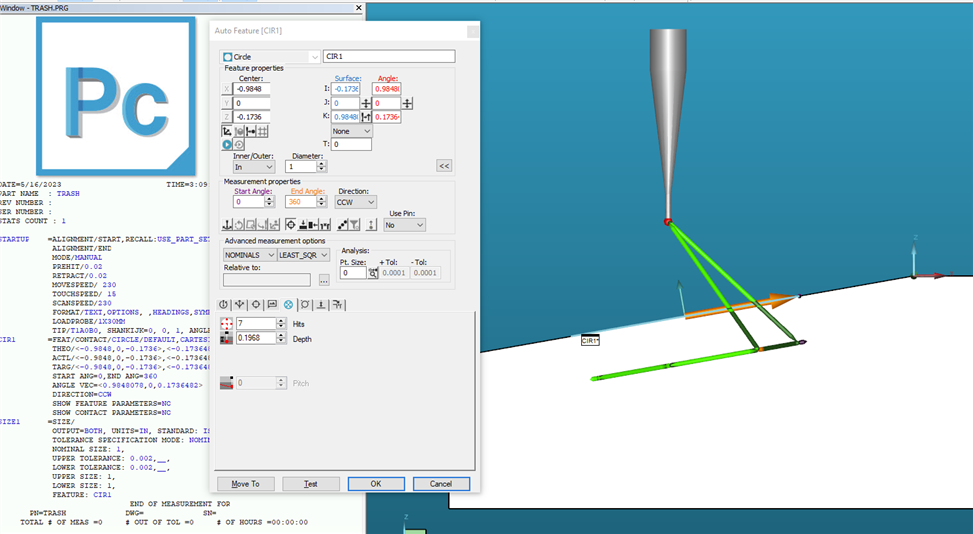
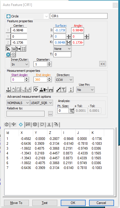
You cannot adjust the Z value with an auto-feature however you can with a 'measured' feature.
place your cursor in the edit window and start typing 'measured', make sure to change from point to circle where the blue text exists. Duplicate the XYZ/IJK/Size that your auto-feature showed. now you can equally space your hits and then adjust the individual z locations. I would continue to select 'no' about updating the feature as you edit the z heights.
Or level to your 10 degree face and make a perfect vector circle 0,0,1 and then level back to the top face and the vectors should change with the new level feature I've had to do that before
Have you tried measuring the circle using a small pitch and then construct a cast circle onto a plane with the correct normal vector? This should work for location but not size. The measured circle itself should give a valid size.
Oddly enough you could measure that feature on an arm and it would calculate it correctly once you established the workplane. Wonder why cmm pcdmis is struggling with it.
When selecting the edge points, YOU MUST EDIT the vectors! After clicking on the edge, change the surface vector to 0,0,1 and change the edge vector so the K vector is zero, Pcdmis will correct the IJ vectors.