hexagon logo

Another Datum Target Points Disaster Print

Good morning all,

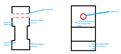
I am looking for some input on how you would program this. Datum A is the midplane of the part using target points at specified locations from Datum B. It doesn't help that Datum C makes zero sense hah, so I left it off of my drawing. I am pretty lost in terms of how to do this correctly (iterative alignment?)...at this point I'm am considering just making planes (with many hit points) and a midplane for Datum A.

Attached Files
  • Datum A would be a width rather than a mid-plane. However, you wouldn't be able to create either of them because you only have 2 points on each datum A surface - you need a minimum of 3 for a plane. Assuming you were able to add a 3rd hit on each datum A surface, the width would constrain 3 degrees of freedom (2 rotations and 1 translation).

    Datum B is a cylinder, perpendicular to datum A and would therefore constrain the remaining 2 translational degrees of freedom.

    This would leave C (which you do not show because you claim it does not make sense?) which would need to constrain the last remaining rotational constraint.
  • Right, I just realized that I can't create a mid-plane for B because I don't have enough points to create planes on each side. I was thinking I could just probe a ton of points on each side of A and ignore the datum target points. It's funny, the engineer is using datum A (and only datum A) for the majority of the FCF's.

    I wanted to do an iterative alignment for this program, but I don't understand how I would do that. Apparently you can't use a cylinder as your primary leveling feature in an iterative alignment. I wanted to somehow mix 3D features (Cylinder) and target points in an iterative alignment.

    What do you think of this: probe Datum B as a cylinder, level and translate to the cylinder. Then probe a random rational line (the print is almost useless for rotation), rotate to that line. Then key in the datum target point locations, create a line on each side of the part using those points, create a mid-line, and translate to the midline.
  • Step 1: Ask engineers for clarification if you're unsure.
    Step 2: Ask for assembly CAD & drawings to see how the datums function within the assembly if they don't explain very well. Based on that decide what type of alignment you need.
    Step 3: Ask how this thing is assembled. If Datum B goes onto some kind of rod & then gets locked at the datum A points use that hole as your primary datum: Make cylinder, level to it & origin in z & y. then take regular hits on datum A & make center plane & origin to x. Rotate either cylinder or the center plane. Not sure where C is so I'm guessing here.
    Step 3: Inspect the CAD model to see if the datum A surface is a flat plane or not. If flat plane don't bother with iterative. Too many people suggest iterative when sometimes it's not needed. Moreover, in this situation it's trickier because you have to make sure you have clearance moves around the workpiece when doing the iterative. I do use iterative from time to time but I don't try to overdo it when it's not really needed. Click on autovector point option & just click around the area a few times where datum A points are indicated on print to see.
  • I just downloaded the document thank you Neil