hexagon logo

Combined position with profile

We have a profile/position combined control we are trying to inspect.(see attached picture)

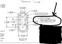
It is legal per ASME Y14.5-2018. section 11-8 "COMBINED CONTROLS" and figure 11-29.

But, my question is how would somoene accomplish this in PC-DMIS.

Sorry, but I've never had to inspect this call-out, and originally thought it was just BS.

Sorry if I posted something incorrectly, it's been awhile since my last post.

Thank you in advance.

Attached Files
Parents
  • Where is datum A? Because when I have something like this on print it implies orientation control like perpendicularity. Engineers get lazy & dump profile callouts everywhere on print thinking it would solve everybody's problem.
  • This particular case is invoking the surface interpretation of position. It's a way of positioning a freeform shape at MMC - the profile of a surface would normally be to no datums and establishes the material boundary for size which is then used in the MMC calculation. As I said, that's not currently supported in PC-DMIS so the best you can do is create two profile of a surface dimensions which would both need to pass in order for the part to conform - the 0.4 to A,B,C is controlling the general location whilst the 0.15 to A controls the size and orientation to a tighter tolerance.
Reply
  • This particular case is invoking the surface interpretation of position. It's a way of positioning a freeform shape at MMC - the profile of a surface would normally be to no datums and establishes the material boundary for size which is then used in the MMC calculation. As I said, that's not currently supported in PC-DMIS so the best you can do is create two profile of a surface dimensions which would both need to pass in order for the part to conform - the 0.4 to A,B,C is controlling the general location whilst the 0.15 to A controls the size and orientation to a tighter tolerance.
Children
No Data