hexagon logo

GD&T Question

See attached image. Datums F and G are in line cylinders. The feature control frame says to check total runout of each F and G to an F-G alignment. This call out has always puzzled me. Doesn't total runout require that you check a feature to one other datum? For example, I could check F to G, or vice versa. How would you check the total runout of these datums to themselves?

Geometric Tolerancing in PCDMIS 2022 is relatively new to me, so I could be doing it wrong, but I've noticed that if I try to dimension a feature that is one of the datum's in the control frame, I get an error telling me I can't do it.

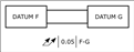
This feature is on a large part, so rotating it is not an option. Both the F and G cylinders are being scanned as circles at various depths. Cylinders are then constructed for both F and G.

So my questions are:

• Is this call out correct?
• If it is correct, how can I construct it to report correctly?
• If it's not correct, what's the best method to check this?

Attached Files
Parents
  • I was not at work when I posted my original question. I had an opportunity to try Neil's suggestion, but I still ended up with an error in creating the dimension. See attached please. Interestingly, I constructed the alignment in legacy as well. How can the total runout of F an G be over 0.25 if those same cylinders are used to construct the F-G cylinder?

    Would it matter if these cylinders were scanned as cylinders, versus being constructed out of scanned circles? I wouldn't think so, but I have to ask.

    Attached Files
Reply
  • I was not at work when I posted my original question. I had an opportunity to try Neil's suggestion, but I still ended up with an error in creating the dimension. See attached please. Interestingly, I constructed the alignment in legacy as well. How can the total runout of F an G be over 0.25 if those same cylinders are used to construct the F-G cylinder?

    Would it matter if these cylinders were scanned as cylinders, versus being constructed out of scanned circles? I wouldn't think so, but I have to ask.

    Attached Files
Children
  • The error message is telling you that the cylinders need to be co-axial. Check that the Y & Z co-ordinates and the ,I,J & K vectors of your F and G cylinders are the same. If F & G aren't in line (different Y & Z co-ordinates) or are skewed (different vectors) that could easily account for the 0.25 error. Don't forget that total run-out also includes form so it might be worth outputting the cylindricity of F & G as well to help you fully understand what is going on.