Just trying to figure this out - when I dimension a circular feature I'll get one size but when adding a GD&T dimension for that same exact feature I get a different size altogether (example below). What's the reason for this?
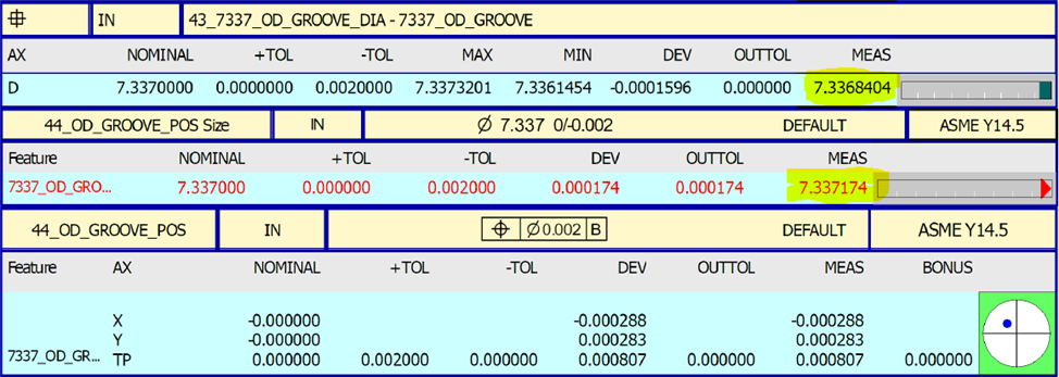
DEFAULT is using the correct math, as defined by the standard you are working to - be that ASME Y14.5 or ISO 1101. Least Sqaures is what people are used to and can give more stable results where there are very few points or where there is "noisy" data, particularly if the amount of measurement uncertainty for your sensor is close to the tolerance value you are trying to verify. That doesn't necessarily mean that it gives "better" results, it is just more stable because it is an average - it depends on your definition of "better".
If you want to ensure that parts will assemble correctly and truly simulate how inspection using hard gauging would function, then measuring your features with dense point distributions that cover as much of the surface as possible and using constrained L2 math (DEFAULT for ASME Y14.5) would be the correct approach.