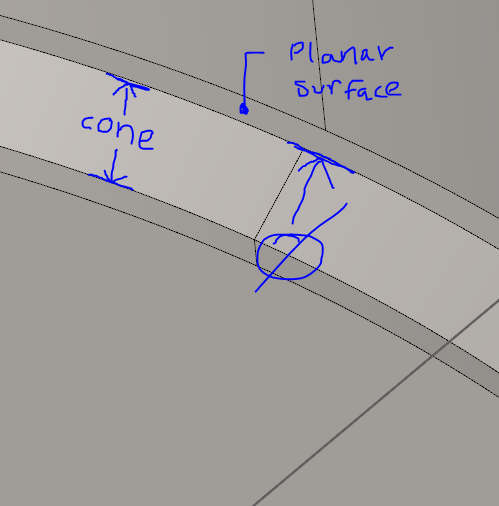
I'm looking to capture a chamfer diameter where it meets a planar surface. I was wondering how a cast circle works from a cone feature and the accuracy. I have a chamfer diameter that I am trying to capture and I saw someone take a cone feature and create a constructed circle from it, using the cast option. The nominals of the constructed diameter look correct. Would this be an accurate way of reporting this dimension on a real part where there are deviations? Where does the Z come from in the cast surface? Trying to avoid having to take more points to create an intersection diameter. Please advise;
A cast circle will inherit the cone's x,y,z,i,j,k and diameter. However, a more accurate approach would be to create an intersection circle between the cone and the plane.
With a constructed circle from a cone be careful. The form of the cone and the flatness of the plane can produce an ellipse. which will affect the reported size of the circle. I would tolerance the roundness of the constructed circle as a reference.
When I do this, I get better results if I measure the hole under the chamfer, make an alignment zero'ing that hole, and then measure the cone. Even better if the chamfer is short, measure the plane first and when I zero out the hole, set the 3rd axis zero on the plane so I know my hits are good on "Z" without a ton of "depth" set for that outermost circle.
Go back to original alignment, keep measuring parts.
Doesn't matter what alignment the intersection is done in.