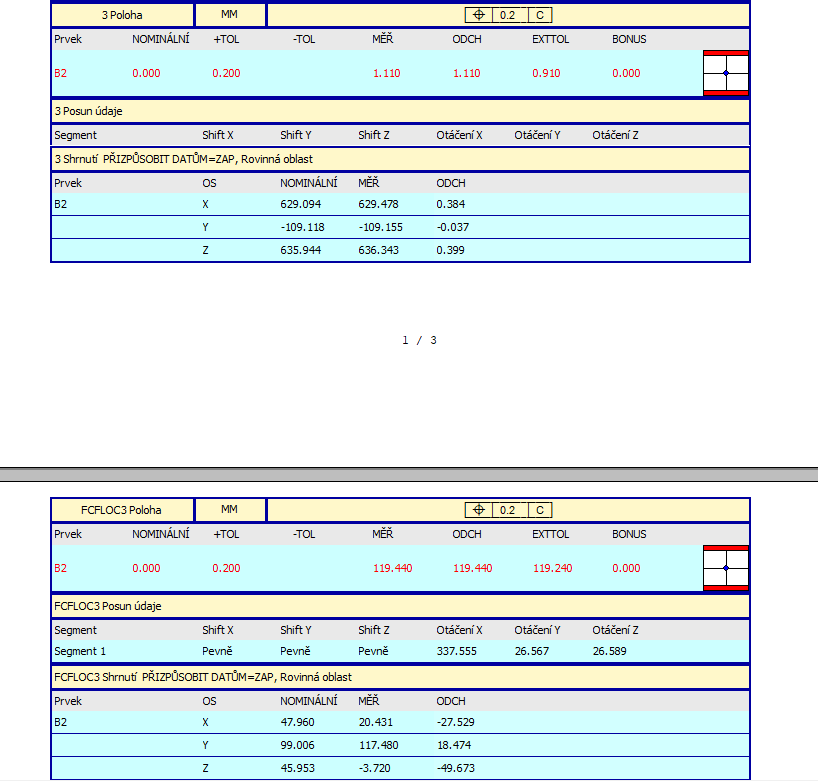
Hi, I don't understand the position evaluation. I have a program where the position of point B2 is evaluated. When I do the evaluation again in that program (without a new measurement) the results are different. Why? The position definition is still the same, I do the same thing 2 times, but the result is different each time. I am desperate..
Select language / english
Select all the prog in the edit wiindow
Copy / paste in a text file
Cut informations (features) that could be "secret" or unusefull for our comprehension.
Copy paste here, and then select "#" around the text to get it as a code.
Select language / english
Select all the prog in the edit wiindow
Copy / paste in a text file
Cut informations (features) that could be "secret" or unusefull for our comprehension.
Copy paste here, and then select "#" around the text to get it as a code.
I'm sorry, but I couldn't send the prg I have a question, is there a manual for evaluating positions/locations? manual where the rules and conditions are written? I searched the internet and couldn't find anything specific. Unfortunately, I probably won't receive training from my employer. I'm trying to understand the principle of position evaluation, but I'm still confused.
position is a cylindrical tolerance zone surrounding the nominal location & vector
A hole (circle) with a vector of 0,0,1 (square to the Z axis) will have deviations in the X and Y axis.
If a hole is 0.5mm off in X and 0.25mm of in Y, then it is .559mm away (RADIALLY) from the nominal location.
The POSITION is toleranced and reported as a DIAMETER.
So the reported position of this example is 1.118mm.
This is the diameter (or cylinder) needed for the hole to be IN TOLERANCE which is then compared to the tolerance. If the position tolerance is only 1mm, then it is out of tolerance.
Then there is the (M) condition of the tolerance. If included, you get to add to the position tolerance the amount the hole SIZE is bigger than the minimum allowed hole size BUT NOT MORE THAN the maximum allowed hole size.
So, hole SIZE is 10mm, +/-0.25mm
The minimum hole size is then 9.75mm and the maximum size is 10.25, maximum bonus tolerance would be 0.5 if the hole is 10.25mm
If the hole SIZE checks 10.1mm, then there will be 0.35mm of 'bonus' tolerance for the hole, giving a total position tolerance of 1.35, and the 1.118 is smaller than that, so it would be in tolerance.
Matthew's explanation is a very brief description of one simple case. Position is not always a cylindrical tolerance zone, it can also be spherical or planar zone. Planar zone can have several different applications also - it can be the distance between two parallel planes, or two radial arcs. Matthew does mention the (M) modifier, which is Maximum Material Condition when applied to the considered feature(s), there is also (L) which is the Least Material Condition. To further complicate things, you can also have (M) or (L) applied to one or more datum, in which case it is the Maximum/Least Material Boundary and datum shift is allowed. I can not emphasize highly enough how important (and useful) training is for this subject. Hexagon has an Applied GD&T for PC-DMIS course that you'd undoubtedly find helpful. As for manuals you can read - take a look at the ASME and ISO standards but, be warned, they're not exactly an easy read.