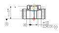
AS shown in the attachment where would the X and Y origin be derived from along the cylinder
, at the middle (orange circle), where the cylinder starts at the face (blue circle) or at the projection/pierce point of [A] (red circle)?
Assuming datum B's axis is pointing along Z, then X and Y will be same at any point along that axis - so it doesn't matter. PC-DMIS will calculate the cylinder's axis direction from all of the hits and fit a cylinder to them. If you level ZPLUS to that cylinder and origin X & Y, any point along the axis will be X=0, Y=0. The THEO and ACTL co-ordinates displayed for the cylinder in PC-DMIS will vary depending on how you've measured it.
Measured cylinders - X,Y,Z are an average of all the hits so it will be the centroid.
Auto-Features - X,Y,Z are at the start point of the cylinder, which is dependent on which end of the cylinder you click when selecting from the CAD model.