hexagon logo

Need help with the function "scan minimum" when creating a circle

I have a part an where I need to measure a contact angle of a circle contacting 2 other circles as well as the radii of these 2 other circles.


At the moment I use 3 scans to achieve this.
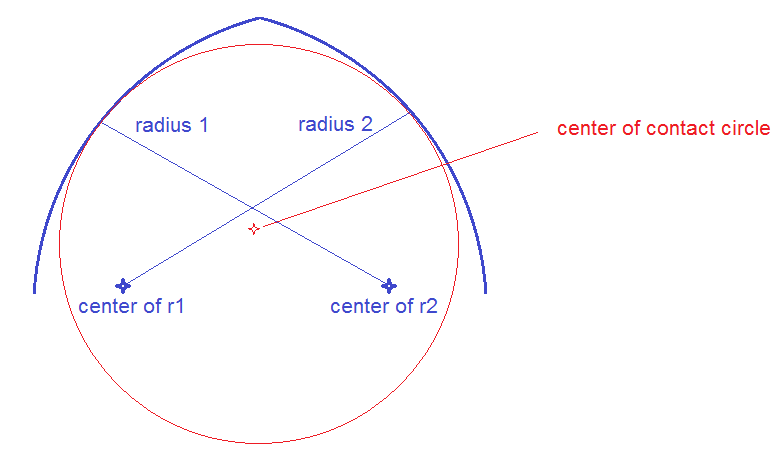
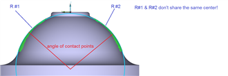
  1. One scan to evaluate the radius #1 (just the left side)
  2. One scan to evaluate the radius #2 (just the right side)
  3. One scan from left to right (over the top surface) to generate a contact circle which contacts a point left and right each to calculate the contact angle. I use the function "scan minimum" to create the contact circle.


One problem I have, is that the scans are a bit rough/jittery. This results in the contact angle not being very stable.

What I want to do now is the following:
  • get rid of the third scan from left to right
  • filter the two separate radius scans
  • generate the contact circle from the two filtered scans

The problem is, that the feature "scan minimum" doesn't allow me to input 2 separate scans.
I tried to generate a a set of the two scans and a point cloud to get around this limitation but nothing works.

Does somebody knows a way to get around this limitation? Maybe there is a way to feed all the pints into one scan?
If possible I would prefer a solution without a script but if necessary I would also resort to a script.
  • KatmandudaMeow

    It is not possible to construct these as spheres.
    See attached picture. (I tried to better visualize the cross-section of this part without the top flat area)

  • ive scanned something similar like this before with an offset center.

    scan radius-constructed as a feature set "each side"-dimensioned each set as profile line "form only least_sqr"

    TTP as sphere at 3 lvls and True Positioned that separately
  • It would appear the contact circle diameter has to be a theoretical gauge size not a measured feature what does the drawing state.
  • Yes, the contact center is a theoretical feature the size is given on the drawing and is always perfect.
    This is the size I have to put in when creating the "minimum scan" circle.

    What changes is the contact angle, depending on the size of the radii and the distance between them.
    I want to make this measurement more stable by removing the jitter of the scan.
  • We evaluate the profile of the whole surface but we also need to evaluate the radius and the contact angle separately.
    The problem is, that the contact circle only gets calculated when I have one scan (from left to right over the top) as soon as I have two separate scans it doesn't work.
    No matter if I create a set or a point cloud.
  • ya the both scans wont construct a circle if both are not exactly perfect in line, i found that out also. kinda weird you cant construct as a sphere or profile the surfaces as form only based off the cads radii
  • Aaron Baldauf There's a limitation with the Scan Minimum command in that it only accepts a single, linear open scan as an input. However, I may have a simple work-around. Rather than creating two separate linear open scans and trying to combine them into one, could you do one linear open scan encompassing all the surfaces you are interested in and then split it into a left & right section? That would allow you to measure everything in one single operation. For the Scan Minimum, you would just use this one scan as the input. For your left and right profiles, you would just construct a left and right set from the relevant hits of the larger scan.
  • neil.challinor

    The biggest problem I have, is that the contact circle (and therefore the contact angle) is not repeatable due to micro-vibrations.
    My goal is to first filter the scan and only then calculate the contact circle.

    As this is a complex scan I don't know how I would filter this scan.
    By splitting it up into its components (2 circle scans), I could use the constructed filter feature and use a Gaussian filter.
  • Another wat of creating the contact angle is by constructing generic features and intersections example below.

    - Measure the two circles
    - Create a 'Z' Vector line with X,Y set as zero (centre of part)
    - Set a local Alignment centred on one of the measured circles
    - Create a generic circle X,Y,Z set Zero, with a diameter calculated by subtracting the theoretical contact circles RADIUS
    as example CIR1.R.MEAS-20 set this for both nominal and measured
    - Construct a pierce point between the generic circle and the 'Z' vector line, you may need to reverse the line to get correct point
    - Construct a line from the measured circle to the Pierce Point

    Dimension line for contact angle.