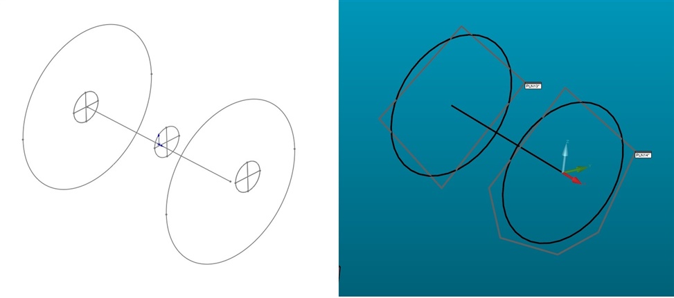
On my older CMM with PC-DMIS 2014, outputting the measurement file as an .iges or .step shows the outline of the measured plane. On my new PC-DMIS portable 2022.2, it outputs these round "targets" instead of the measured plane outline. Is there a setting I can set the plane output style? Attached is what the measured outline looks like in PC-DMIS versus what gets outputted in a CAD file.
If you measure the auto plane with To Points you can get the points of the planes exported if thats what you need, or attach a reference plane to the "targets" in your 3D CAD software.
If you measure the auto plane with To Points you can get the points of the planes exported if thats what you need, or attach a reference plane to the "targets" in your 3D CAD software.