hexagon logo

Ghost Features Showing Up in Scans; Hexagon Romer Arm (85)

Hello, I tried searching for this on the forum to see if this has been covered already, but I might be using the wrong terminology: I am new to CMM and have been given the opportunity because I have a lot of computer experience and a college degree. I also operate a goniophotometer and compared to the CMM it is a literal dream; despite the simplicity of the task, I am having a lot of trouble getting good scans and then it seems that even those that are good might not be valid when aligning them with a part in a CAD file.

Training has been a patchwork of teams meetings and calls and the former operator coming down in his free time to try and help me out. Formal training seems like it will come later but no timetable has been set and worse I have already been given several tasks that are actually important and have to be done well before I am to receive training.

Currently, the RDS is set to automatic at 50%. It was originally at 25% but that was too low and changing it at least solved some of the resolution problems we were having. The parts in question are black plastic housings for a light fixture. They require scanning as quality from higher up in the company suspect that there might be deformation along the vibratory welding channels for where the lens is supposed to sit. With the arm and PC-DMIS in theory this can solve the issue without question, but despite being close to accomplishing the task I am being held up by several issues that a quick teams meeting is not going to solve.

The most important issue is that when attempting to scan the welding channel I end up having to run over the channel in several different directions in order for the arm to register the features it is scanning over. By itself that is no problem, but as a consequence the arm ends up registering features that suggest the housing was moved over by half an inch or more, and after it has been processed by PC-DMIS there is no way to get rid of it - even more annoying further scans do not fill in these ghosts areas anyway, so it ends up looking like a 'shadow' that the arm picked up somehow and obviously this is not only bad data but when I generate reports the customer and my bosses are not going to want to see it. I also suspect it interferes in the alignments when I go ahead and use that data anyway.

Is there a way to either delete these features or avoid creating them entirely? The welding channels and the walls of the channels have to be scanned and after alignment (its own separate problem) there have to be annotation points in order to see how the cavities are deviating from the cad file and how far out of tolerance they are.

This brings me to my second issue: I am not sure what maximumSTD and maximumDist mean as the data is processed. Because I am in the dark in this area I end up being unsure if the data I do get from the good scans I occasionally get is actually valid when aligned against the CAD. For example, the tolerances are .005+/- and I depending on the value I use for maximum distance, I get data that is either within tolerance or outside of it which makes me think that if I use the wrong value I will end up with invalid data.

When it comes to maxSTD I have no idea what it does other than the computed alignment seems to vaguely change though I admit that it never changes in a way that obviously invalidates the alignment.

Is there anything I can do to resolve these issues before I am sent to actual training?
  • What hardware do you have in terms of laser scanner on the arm? RS6?
    What RDS version are you running alongside PC-DMIS? Tried updating it to a newer one?
    You might want to try a scanning spray to see if that will make the scanner pickup the surfaces.
  • What hardware do you have in terms of laser scanner on the arm? RS6?
    What RDS version are you running alongside PC-DMIS? Tried updating it to a newer one?
    You might want to try a scanning spray to see if that will make the scanner pickup the surfaces.


    We have RS5 version 6.2; as far as I am aware it is the more up to date version of the software. We do use a spray - dr scholls from a demo of the arm my bosses went to.
  • There is an update to RDS that is 6.3. I don't recommend updating to it as it kept triggering a message saying that there was a system update, but none to be found... Reverted back to 6.2.3 and all is fine again.
    Try changing the distance to the part (move closer/further away) when scanning the ghost surface.

    Maybe try dry schampoo / real scanning spray or spray a thicker layer with the Dr Scholls.


    Gotcha I will forgo the update part then - changing the distance and orientation does help some; mostly it seems like getting the part directly into the overhead light has helped the most though I am not sure that is supposed to happen or be a factor. On the spray part you are exactly right: I think it is the generator of many of the problems as it was not made for CMM but once they saw it work at a demo I think they were convinced it was, 'good enough'.

  • What sensor are you running for collecting data? you mention a scan, so it's obviously not a TTP sensor.

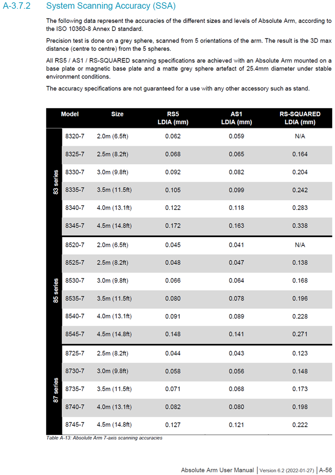
    Most of the Romer arm hardware is not capable of reproducing data precise enough to discern pass/fail for a 0.010" total tolerance feature.
    RS5 scanners are reproducible from ±0.044mm (0.0017") to ±0.172mm (0.0068"),
    AS1 scanners are reproducible from ±0.041mm (0.0016") to ±0.163mm (0.0064")
    --depending on the arm length and series it's mounted to.

    Here's a snip directly from hexagon romer arm manual


    You might be stuck using a wooden ruler, for dimensions that only a caliper can effectively quantify. This might be a case of the wrong tool for the job.
  • What sensor are you running for collecting data? you mention a scan, so it's obviously not a TTP sensor.

    Most of the Romer arm hardware is not capable of reproducing data precise enough to discern pass/fail for a 0.010" total tolerance feature.
    RS5 scanners are reproducible from ±0.044mm (0.0017") to ±0.172mm (0.0068"),
    AS1 scanners are reproducible from ±0.041mm (0.0016") to ±0.163mm (0.0064")
    --depending on the arm length and series it's mounted to.

    Here's a snip directly from hexagon romer arm manual
    {"data-align":"none","data-size":"full","title":"image.png","data-attachmentid":535177}

    You might be stuck using a wooden ruler, for dimensions that only a caliper can effectively quantify. This might be a case of the wrong tool for the job.


    The RS5 is I believe what it is called: it is the one that has a red line and a red dot you must keep in alignment to get data. If I am understanding you correctly, did my bosses basically request a tolerance that the ARM is not capable of gathering data for? The tolerance is +/- .005mm and by looks of what you mentioned it seems that places all of our data within the margin of error of the tolerances possible with the RS5.
  • Those tables must be covering both the sensor and the arm together. Question is, what is the uncertainty?
  • yeah basically. you are checking a dimensional value, with a tool that cannot discern even one sigma level of that entire tolerance.
    Part tolerance ==== |<---x--->| (0.01MM)
    System resolution = |<--------------------x-------------------->| (0.044mm at best)
  • Those tables must be covering both the sensor and the arm together. Question is, what is the uncertainty?


    I am not sure what you are asking.
  • it's in my opinion, intentionally vague. the manual has the sensor's reproducibility quantified independently to a cal sphere which claims to be reproducible to 0.004mm -at best- from what i recall last week. But that doesn't mean anything without knowing the reproducibility of the arm it's mounted on, and the error contribution it adds to the results...