I have a bore that is Datum B. It has a perpendicularity callout to Datum A, which is a flat surface. So, I have to measure it as a cylinder. I have another bore that has a circular runout callout to AB. So do I have to measure B again as a circle? Because I would have to assign that as another datum to build the feature control frame. But if I just use B as a cylinder, then wouldn't it be measuring total runout and give me a different result than circular runout?
I don't recall if Xact "slices" the cylinder IF the toleranced feature IS a cylinder and the tolerance is single runout. Maybe
neil.challinor can chime in to fill in the blanks.
Legacy does not do this, so if you choose a cylinder for a single runout, legacy will give you the worst runout over the length of the cylinder = total runout. Here, you as the operator must choose circles as the toleranced feature since the software isn't taking the source feature type into consideration. This means that you must MEASURE them as circles and evaluate them as circles.
GeoTol however, works fine with single runout with a cylinder as toleranced feature since the invisible helping hand will slice the cylinder (recommended to measure the cylinder with concentric circles) and evaluate these sliced circles and report the worst runout of these circles.
I corrected my post above. I failed to mention that the old programs were measuring the circular runout of a bore or turn by simply measuring them as one SINGLE circle. If I understand it, that's not correct since it's only taking a single "slice" of the cylinder. This is what I'm afraid to bring up since it likely means that they were sending non-conforming parts for years and I, as a rookie, have to call them out for it.
Now I'm more confused that ever. I measured the cylinder by first measuring 10 individual circles at different depths, then constructing a cylinder out of those 10 circles. I dimensioned the runout of the constructed cylinder as well as the runout of each circle. I thought the circular runout would be the worst individual circle and the total runout would the difference of the highest max and the lowest min. Except the total runout actually measures LOWER than any individual circle. Maybe I'm really not understanding it or I'm just not programming it correctly.
DATUM C =FEAT/CYLINDER,CARTESIAN,OUT,LEAST_SQR,NO
THEO/<0,-48,0>,<0,-1,0>,122,26
ACTL/<0.384,-48.027,0.011>,<0.0013391,-0.9999991,-0.0001401>,122,26
CONSTR/CYLINDER,BF,DATUM C 3MM,DATUM C 6MM,DATUM C 9MM,DATUM C 12MM,DATUM C 15 MM,DATUM C 18 MM,DATUM C 21 MM,DATUM C 24 MM,,
FCFRNOUT1 =CIRCULAR RUNOUT : DATUM C
FEATCTRLFRAME/SHOWPARAMS=YES,SHOWEXPANDED=YES
CADGRAPH=OFF,REPORTGRAPH=OFF,TEXT=OFF,MULT=10.00,A RROWDENSITY=100,OUTPUT=BOTH,UNITS=MM
CUSTOMIZED DRF=NO
STANDARDTYPE=ASME_Y14_5
DIMENSION/CIRCULAR RUNOUT,RADIAL,0.1,B
NOTE/FCFRNOUT1
FEATURES/DATUM C,,
FCFRNOUT3 =CIRCULAR RUNOUT : DATUM C 3MM,DATUM C 6MM,DATUM C 9MM,...
FEATCTRLFRAME/SHOWNOMS=NO,SHOWPARAMS=YES,SHOWEXPANDED=YES
CADGRAPH=OFF,REPORTGRAPH=OFF,TEXT=OFF,MULT=10.00,A RROWDENSITY=100,OUTPUT=BOTH,UNITS=MM
CUSTOMIZED DRF=NO
STANDARDTYPE=ASME_Y14_5
DIMENSION/CIRCULAR RUNOUT,RADIAL,0.1,B
NOTE/FCFRNOUT3
FEATURES/DATUM C 3MM,DATUM C 6MM,DATUM C 9MM,
DATUM C 12MM,DATUM C 15 MM,DATUM C 18 MM,
DATUM C 21 MM,DATUM C 24 MM,DATUM C 27 MM,
DATUM C 29 MM,,
FCFRNOUT7 =TOTAL RUNOUT : DATUM C
FEATCTRLFRAME/SHOWPARAMS=YES,SHOWEXPANDED=YES
CADGRAPH=OFF,REPORTGRAPH=OFF,TEXT=OFF,MULT=10.00,A RROWDENSITY=100,OUTPUT=BOTH,UNITS=MM
CUSTOMIZED DRF=NO
STANDARDTYPE=ASME_Y14_5
DIMENSION/TOTAL RUNOUT,RADIAL,0.1,B
NOTE/FCFRNOUT7
FEATURES/DATUM C,,
COMMENT/REPT,
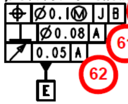
Maybe I missed it, or didn't understand it. I have a FCF with three requirements in it. It calls position of a bore to two datums. It then calls perpendicularity of the same bore to the same plane being used in the positional callout, to 0.08mm. Then it calls runout of that same bore to the same plane to 0.05mm. Is this something that came out of the office of the redundancy office, or do I just not understand it?
I'm using 2022.2 and attempted to dimension this using Geometric Tolerancing, but it wouldn't allow it, so I went back to Legacy, which is my preference anyway. It "seems" they attempted to make dimensioning easier, or more compliant might be a better word, but there appears to be a lot of stipulations in using it. By that I mean it will only work properly, "if this is that..., and that other thing isn't this type of thing..., with the exception being..., but only if this condition is true...etc". Seems too convoluted to use effectively. Of course it may just be because I'm too used to Legacy. Right or wrong, my reasoning is that I've used Legacy for nearly 20 years. It's dimensioned hundreds of parts that have passed PPAP and are still being used today, so it can't be "wrong", just different.
In addition to that, I am kind of gun shy after Hexagon came out and said their math was wrong in Xact Measure. At least that's how app support has described the reasoning for the upgrade to Geometric Tolerancing, to me. Does anyone else share that same aversion to Geometric Tolerancing over Legacy?
Thanks in advance for your comments.
The Hermit, Are you able to share the drawing (or a sketch) showing the datums, the feature and the callout's you are tying to verify? When you say the Geometric Tolerance command "wouldn't allow it", what wouldn't it allow? What error message(s) do you see and for which callout? From your description, I suspect it's this...
Then it calls runout of that same bore to the same plane to 0.05mm
The datum reference frame for a runout tolerance needs to define an axis of revolution because runout analyses radial deviation from that axis. If you only had a primary datum plane, there would be no centre of rotation which is why the Geometric Tolerance command would not allow it. Although legacy won't give you any error messages, you would still have problems with the results. Strictly speaking, you would need to recall the initial, machine coordinate alignment (usually called "STARTUP") and then level to you datum plane. Although the plane would set the orientation, your feature would be nowhere near the origin and your results would be huge. The problem with legacy is that it is based on the active alignment and alignments inherit certain information from previous alignments. This can sometimes mask mistakes. For example, in this case, I suspect you have recalled whatever alignment was currently active in your routine (one which was already levelled, rotated and origined to features and more-or-less centred on the cylinder you are reporting) and then levelled to the datum plane before reporting runout. Alternatively, you may have selected the "use datums" checkbox and picked the plane as the datum but this would still be creating a new alignment in the background in the same way I just described. This means that you have actually, without realising, added a secondary datum, not shown on your drawing - you have origined to whichever feature was used in your prior alignment. Although this may give
"good" results, it does not mean that they are correct. How do you know that what you have done is what the designer intended?
The Hermit, Are you able to share the drawing (or a sketch) showing the datums, the feature and the callout's you are tying to verify? When you say the Geometric Tolerance command "wouldn't allow it", what wouldn't it allow? What error message(s) do you see and for which callout? From your description, I suspect it's this...
Hi Neil, here is the callout. Everything here, but the runout makes sense to me. E is a bore and A is a plane. When I say it wouldn't allow it, what I mean is that when I select runout, the E bore is available in the feature list, but the A datum is not, whether I select E as a circle or a cylinder.