I have a bore that is Datum B. It has a perpendicularity callout to Datum A, which is a flat surface. So, I have to measure it as a cylinder. I have another bore that has a circular runout callout to AB. So do I have to measure B again as a circle? Because I would have to assign that as another datum to build the feature control frame. But if I just use B as a cylinder, then wouldn't it be measuring total runout and give me a different result than circular runout?
Thanks. Before my current job, I worked at a place that did fabricated parts from a brake press with sheet metal and had never seen runout before. I'm struggling to understand it.
I understand completely. Worked as a programmer measuring exhaust systems. My current job has multiple exhaust fan assemblies and furnace wheels so there is a lot of runout parts. I had the same challenge as you. had to learn it and understand it but it definitely takes some time and brain power. You cant know something you don't know..... ya know? lol
Good luck and if you don't have one already.... grab a copy of y14.5. I may not comprehend everything in the book but ive been able to establish a pretty solid understanding of most GD&T.
Notes:
- datum feature B (cylinder) and the toleranced feature (cylinder) must be measured perpendicular to their respective centerlines
- measure the toleranced feature using the concentric circles strategy to be sure that the measure strategy does not conflict with the tolerance evaluation (helical strategy/cylinder lines should not be used here)
- depending on the strategy used and the evaluation type (legacy/Xact/GeoTol), the result you get could be total runout
Imagine using a record player to listen to some of your favourite music on classic vinyl.
When you put the stylus on the record, you'll notice it moving up and down as the record spins - that's runout of the plane.
If the record isn't quite central on the turntable, you'll also notice the stylus moving towards and away from the centre as the record spins - that's circular runout.
With my above example being said...Measure -A- as a plane, -B- as a cylinder, and your evaluation diameter as a cylinder. You need 3d features so the software can evaluating the entire form of the datums back to the feature & not just one circular element on the bores
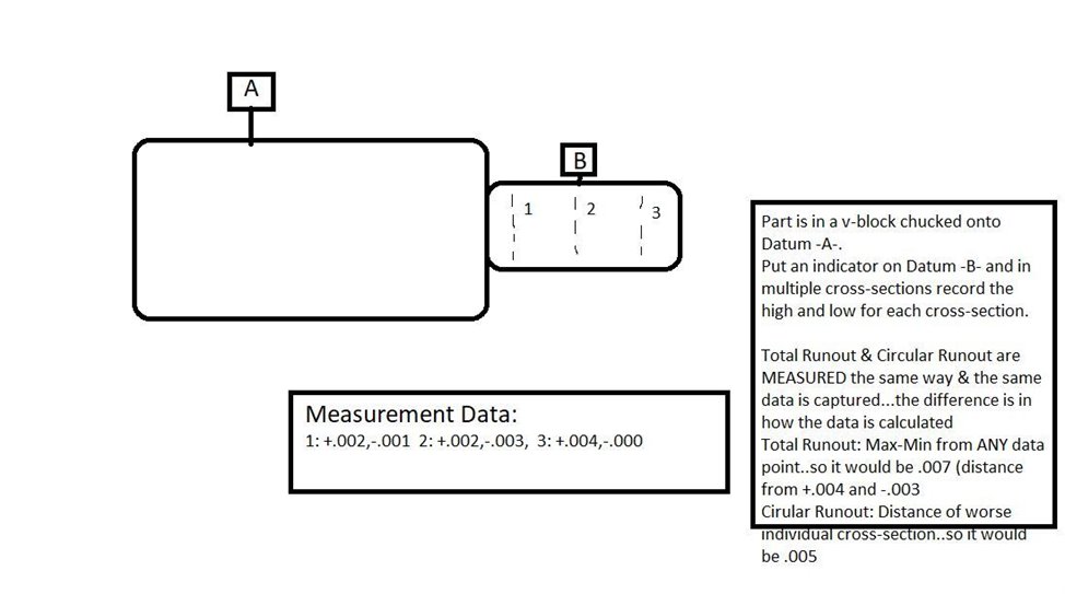
Ok, here's my next question. I have a part that looks kinda like my drawing below. It has two cylinders, one Datum B and the other Datum C. It wants the circular runout of C to B. I get that I have to measure B as a cylinder, but how about C? Do I measure that as a circle, cylinder, or both, since I also need the perpendicularity of it? I measured C as 3 circles and constructed a cylinder out of them because I also wanted to see the diameter at multiple levels since it's so tall. I measured the circular runout of that constructed cylinder and it was at 0.118, which is out of tolerance. The total runout was exactly the same. I measured the circular runout of each of the 3 circles, and the worst one was 0.118, same as the circular and total runout of C as a cylinder. Was I wrong to measure C like that? Should I have just done a measured cylinder and not a constructed one? Sorry if that's a lot to ask, I'm just trying to figure out if this part is good or bad.
Edit: Yes, I know the tolerence for that total runout is wrong per my drawing, but it's the deviation that I'm looking at.
Since you want to know the perp of C, it must be measured as a cylinder or several circles that are used to create a cylinder used in the perp eval (and total runout).
Your user profile says that you are running 2017 so will have to measure it as several circles - enough to give a good representation of the full extent of the surface and with a high enough point density to capture the form error. Evaluate circular runout for each one and look for the worst value out of all of them to determine pass/fail. For the perpendicularity, construct a BFRE cylinder from the hits of all of your circles.
XactMeasure & Legacy Dimensioning are unable to extract circular cross sections from cylinders. That is why, when you dimension circular runout of the cylinder, it gives you the same number as total runout - it's looking at all of the hits combined rather than each cross-section independently.
So if XactMeasure can't evaluate circular runout from a cylinder and will always report total runout, why is there even a circular runout option?
For some context, I'm trying to create a program for a part that will measure the complete and finished part. Prior to my arrival a few months ago, they had multiple programs for different machining operations. In comparing my reports to the previous programs, it seems the runout results are vastly different. A lot of them get circular runout by measuring a bore or a turn as a SINGLE circle. And some of them (including the one I'm comparing mine to) use a circle for a datum reference rather than a cylinder. If I'm understanding it correctly, neither are correct.
I have a feeling that the company I work for has been measuring runout incorrectly for years. So I have a dilemma here. Do I rock the boat and bring it up to them? I have a feeling my supervisor won't be happy with me and/or won't believe me. He doesn't trust the CMM any farther than he can throw it.