So I want to setup AB alignment here. Holes with 'K' are -B- Datums. I want to set rotation using -B- holes but dont want to rotate to that line between them. In Calypso I was able to do this. How in PC Dmis?
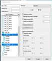
OFFSET line will do it, construct feature, line, select the 2 circles, then click on OFFSET, then either enter offsets or have it calculate the offsets based on the vector you want the line to have. YOU MUST have the correct nominals for both circles in the circles (as in, pick them from cad).
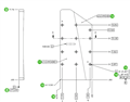
-Load model in the same orientation shown & put the part on the machine like that as well
-Find the part using a simple readpoint alignment or something similar. Once the part is found...
-Probe a plane on -A- (PLN_A)
-Probe both circles for -B- (CIR_B1 and CIR_B2)
-Create an offset line from CIR_B1 to CIR_B2 with an offset value of X-7.07. This will create LIN_B with a perfect 0,1,0 vector
-Create new alignment and all at once...Recall startup...Level ZPLUS to PLN_A...Rotate LIN_B YPLUS about the ZPLUS, X&Y Origin is CIR_B1 and Z Origin is PLN_A...Offset X+ 0.505...Offset Y-3.897
-Now you're constrained to the datum structure with your "0" at blueprint nominal
I''m not 100% on this but you will likely need to do one of two things:
-Make it a 2d Line.
Or
-Create that line, then construct an additional line from it defined as an offset line, with the provided X -7.07 offset.