hexagon logo

Projected Tolerance Zone

I've seen this question asked, but I can't find an answer to my specific question. It used to be that the FCF would have a P modifier in it to indicate you need to project your feature. As of late I'm seeing "TOL. ZONE PROJ. .620". Are the two methods of doing this different, or just a horse of a different color?

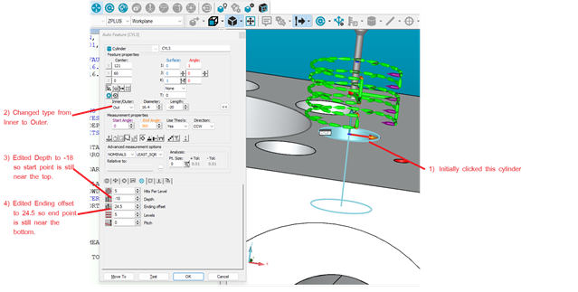
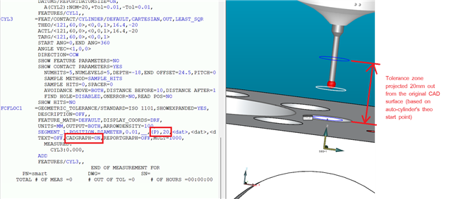
If I select "axis average" and enter .620 in the box on a cylinder, I can see the projected length in the dimension. I don't see that same thing if I use it on a circle. I'm using legacy for this in 2022.2. I've seen others say you can use it from a drop down box in Geometric Tolerancing, but I don't see an option for that in there.

Last question. Can you create a generic plane, dependent on the datum plane, add 0.62" to the location, then construct circles between the bolt hole pattern the generic projected plane to get the same result?

Either way, if someone could help me figure out the "right" way to do this, I'd appreciate it. See attached image please.

Thank you

Attached Files
  • It depends how you've programmed it.  If you use an auto-cylinder and select the hole on the CAD model, then change the type from inner to outer and edit the depth/ending offset, it should work.  However, if you edit the X,Y,Z,I,J,K or length then the theoretical start and end points will be wrong.  Turning CAD graphics on in the position dimension will let you see where the tolerance zone is and determine if it's right or not.

    In the following example, I selected the CAD and then made edits so that the the theoretical start and end points and the measurement direction remained the same (top to bottom)...

    Turning on CAD graphics in the Geometric Tolerance dimension shows the correctly projected tolerance zone...

  • Thanks, man, I really appreciate the info.  I typically will do what you said regarding changing inner to outer while altering my depth/ending offset.  The only nominal I ever change in that scenario is the diameter (bc the JoPlug diameters always vary).  I never utilized the CAD graphics in the Geo Tol dimensioning, though, and that's something I'll be doing moving forward.  I also appreciate the visual aids.  Thanks again.