hexagon logo

Highest point /Theoretical datum plane from radius

Hi, how would i construct a datum/alignment from the highest point on a radius
And how would i get the right orientation for the dimension

Posting pic of datum and the callout/ boxed dimension

Attached Files
    1. Measure a plane on datum A and then level ZPLUS to it.
    2. Measure datum D, origin X & Y on it.
    3. Measure a plane on datum B and then Rotate XPLUS to it.
    4. Add a rotation offset to rotate back by whatever the theoretical angle is between B and the vertical centre line.
    5. Scan around the R7 surface at multiple depths, ensuring you capture enough points to accurately represent the surface. The point density of your scans needs to be sufficiently high to be sure you capture the high point and the distance between scans needs to be close enough to be sure to capture any surface variation across the full depth of the radius.
    6. Construct a SET from all of your R7 scans.
    7. Your user profile says you are running 2011/ 2019 so you will need to use the MININDEX or MAXINDEX function to pull the highest point in Y from your SET / COP. (If you were running 2021.2 or newer, you could use the constructed extreme point)
    8. Construct a generic plane passing through the high point.

    Example code...
    PLN1       =FEAT/PLANE,CARTESIAN,OUTLINE
                THEO/<0.125,-0.375,0>,<0,0,1>
                ACTL/<0.125,-0.375,0>,<0,0,1>
                MEAS/PLANE,4
                  HIT/BASIC,NORMAL,<10.5,0,0>,<0,0,1>,<10.5,0,0>,USE THEO=YES
                  HIT/BASIC,NORMAL,<0,10.5,0>,<0,0,1>,<0,10.5,0>,USE THEO=YES
                  HIT/BASIC,NORMAL,<-10,3,0>,<0,0,1>,<-10,3,0>,USE THEO=YES
                  HIT/BASIC,NORMAL,<0,-15,0>,<0,0,1>,<0,-15,0>,USE THEO=YES
                ENDMEAS/
    A1         =ALIGNMENT/START,RECALL:STARTUP,LIST=YES
                  ALIGNMENT/LEVEL,ZPLUS,PLN1
                  ALIGNMENT/TRANS,ZAXIS,PLN1
                ALIGNMENT/END
    CYL1       =FEAT/CYLINDER,CARTESIAN,OUT,LEAST_SQR
                THEO/<0,0,-5>,<0,0,1>,14,10
                ACTL/<0,0,-5>,<0,0,1>,14,10
                MEAS/CYLINDER,8
                  HIT/BASIC,NORMAL,<7,0,-10>,<1,0,0>,<7,0,-10>,USE THEO=YES
                  MOVE/CIRCULAR
                  HIT/BASIC,NORMAL,<0,7,-10>,<0,1,0>,<0,7,-10>,USE THEO=YES
                  MOVE/CIRCULAR
                  HIT/BASIC,NORMAL,<-7,0,-10>,<-1,0,0>,<-7,0,-10>,USE THEO=YES
                  MOVE/CIRCULAR
                  HIT/BASIC,NORMAL,<0,-7,-10>,<0,-1,0>,<0,-7,-10>,USE THEO=YES
                  MOVE/CIRCULAR
                  HIT/BASIC,NORMAL,<0,-7,0>,<0,-1,0>,<0,-7,0>,USE THEO=YES
                  MOVE/CIRCULAR
                  HIT/BASIC,NORMAL,<-7,0,0>,<-1,0,0>,<-7,0,0>,USE THEO=YES
                  MOVE/CIRCULAR
                  HIT/BASIC,NORMAL,<0,7,0>,<0,1,0>,<0,7,0>,USE THEO=YES
                  MOVE/CIRCULAR
                  HIT/BASIC,NORMAL,<7,0,0>,<1,0,0>,<7,0,0>,USE THEO=YES
                ENDMEAS/
    A3         =ALIGNMENT/START,RECALL:A1,LIST=YES
                  ALIGNMENT/TRANS,XAXIS,CYL1
                  ALIGNMENT/TRANS,YAXIS,CYL1
                ALIGNMENT/END
    PLN2       =FEAT/PLANE,CARTESIAN,OUTLINE
                THEO/<10.78,-8.065,-5>,<0.9659258,-0.258819,0>
                ACTL/<10.78,-8.065,-5>,<0.9659258,-0.258819,0>
                MEAS/PLANE,4
                  HIT/BASIC,NORMAL,<12.074,-3.235,-2>,<0.9659258,-0.258819,0>,<12.074,-3.235,-2>,USE THEO=YES
                  HIT/BASIC,NORMAL,<12.074,-3.235,-8>,<0.9659258,-0.258819,0>,<12.074,-3.235,-8>,USE THEO=YES
                  HIT/BASIC,NORMAL,<9.486,-12.894,-8>,<0.9659258,-0.258819,0>,<9.486,-12.894,-8>,USE THEO=YES
                  HIT/BASIC,NORMAL,<9.486,-12.894,-2>,<0.9659258,-0.258819,0>,<9.486,-12.894,-2>,USE THEO=YES
                ENDMEAS/
    A2         =ALIGNMENT/START,RECALL:A1,LIST=YES
                  ALIGNMENT/ROTATE,XPLUS,TO,PLN2,ABOUT,ZPLUS
                  ALIGNMENT/ROTATE_OFFSET,15,ABOUT,ZPLUS
                ALIGNMENT/END
    SCN1       =BASICSCAN/CIRCLE,NUMBER OF HITS=8,SHOW HITS=NO,SHOWALLPARAMS=NO
                ENDSCAN
    SCN2       =BASICSCAN/CIRCLE,NUMBER OF HITS=8,SHOW HITS=NO,SHOWALLPARAMS=NO
                ENDSCAN
    SCN3       =BASICSCAN/CIRCLE,NUMBER OF HITS=8,SHOW HITS=NO,SHOWALLPARAMS=NO
                ENDSCAN
    SCN4       =BASICSCAN/CIRCLE,NUMBER OF HITS=8,SHOW HITS=NO,SHOWALLPARAMS=NO
                ENDSCAN
    SCN5       =BASICSCAN/CIRCLE,NUMBER OF HITS=8,SHOW HITS=NO,SHOWALLPARAMS=NO
                ENDSCAN
    SCN6       =BASICSCAN/CIRCLE,NUMBER OF HITS=8,SHOW HITS=NO,SHOWALLPARAMS=NO
                ENDSCAN
    SCN7       =BASICSCAN/CIRCLE,NUMBER OF HITS=8,SHOW HITS=NO,SHOWALLPARAMS=NO
                ENDSCAN
    SCN8       =BASICSCAN/CIRCLE,NUMBER OF HITS=8,SHOW HITS=NO,SHOWALLPARAMS=NO
                ENDSCAN
    SCN9       =BASICSCAN/CIRCLE,NUMBER OF HITS=8,SHOW HITS=NO,SHOWALLPARAMS=NO
                ENDSCAN
    SCN10      =FEAT/SET,CARTESIAN
                THEO/<-4.231,-19.671,-5>,<0,0,1>
                ACTL/<-4.231,-19.671,-5>,<0,0,1>
                CONSTR/SET,BASIC,SCN1,SCN2,SCN3,SCN4,SCN5,SCN6,SCN7,SCN8,SCN9,,
                ASSIGN/V1=MININDEX(SCN10.HIT[1..SCN10.NUMHITS].Y)
    F1         =GENERIC/PLANE,DEPENDENT,CARTESIAN,$
                NOM/XYZ,<0,-19.8,0>,$
                MEAS/XYZ,<SCN10.HIT[V1].X,SCN10.HIT[V1].Y,SCN10.HIT[V1].Z>,$
                NOM/IJK,<0,-1,0>,$
                MEAS/IJK,<0,-1,0>​
    
  • Looks like a good time to build a fixture. Simulate Datum B and C with the fixture and save yourself the time measuring all those scans.

    Also, how bad is the auto high point at finding high points?
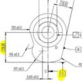
  • To Jefman's point, there isn't a connection shown between Datums -B- and -C- orientation to each other or -C- to the part. And the FCF callout is single segment, which means those measurements are independent of each other. The top half would be spatial and origin on -A-, rotation and origin on -B-, and the bore would be allowed to best fit along the -B- axis/direction. The second callout would be the same principle as the top, only using -C-. The problem I see is what is the orientation of -C- to the rest of the part? There's no angle shown and unless there's a flat section on the -C- surface, how do you know what the angle is to rotate/evaluate to?
  • There is its 12.5 degrees, just forgot to capture it in the picture
  • Thanks, i have tp200 probe, but i guess i can make a "zig zag" scan or whatever its called(?)
    also im using 2019 offline and 2011 CAD, so i dont think i have alot of scanning options to choose of.
    Can i just use a bunch of vector points at R7 with a high density and construct a set of those points instead?
  • Yeah, that would be better option.
    Unfortuantly its only a prototype and we ll only make 3 parts (and its due tomorrow...)
    But ill try to do that if we get serial production of the part
    ty for ur input
  • Sorry i forgot to include the boxed angle in the snap, its 12.5 degrees
  • So you can define the direction of C, and then search the max point along this direction...
  • ok =) so just like Neils explanation
    ty jeffo