hexagon logo

Hole pattern position to a plane only

Looking for interpretation of the attached true position call out for a 4-hole pattern. I am not well versed in GD&T but know enough to get myself in trouble.

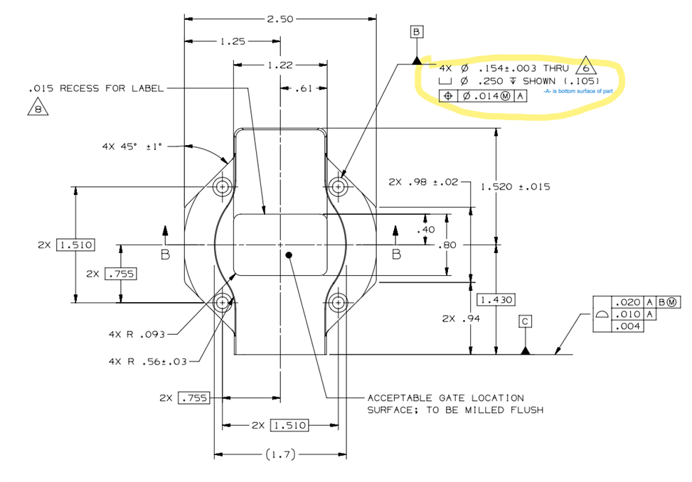
I've staged the part and aligned with the bottom as -A- (level and origin Z).
I probed and created 4 cylinders, then created circles at the intersections of the cylinders and -A- respectively, then used the circles to create one circle -B- and translated X,Y to -B-.
I probed plane -C- and controlled rotation around Z with plane -C-.

My question is; How is the true position calculated / reported in this case, when there are multiple holes making up one datum in reference to a plane only?

Thanks.

​ ​

Attached Files
  • This is a best fit of the 4 holes while staying level to datum A. Are you using Geotol or reporting in legacy? Rotation will be set by the 4 holes. Think about setting the part on the a datum surface, putting 4 bolts in to the holes. At that point you will not be able to rotate the part any more (too a small degree depending on hole size and bolt size. Not even really sure why there is a C datum in this case. But hard to say without seeing an actual part and how it works.
  • I always find it useful to figure out what a hard gage would look like from the datums indicated. In this case there would be a flat plate with four .151 pins spaced at the Basic dimednsions apart.
  • I'm using Geotol in version 2020 R1. The part is a molded motor cover that mounts to a block. Datum -C- is a plane containing four threaded inserts and a clearance hole of which I am uncertain what it connects to.

    I'm uncertain how to calculate the position. Do I use the basics and report a position result for each hole?


  • I'm using Geotol in version 2020 R1.


    If you are running 2020 R1 then you are using XactMeasure, not Geotol. Geometric Tolerance comamnds ("Geotol") were introduced in 2020 R2.

    XactMeasure was more limited than the Geometric Tolerance command but it was still possible to measure the hole patterns shown in your screenshots. For the pattern of 4 holes to datum A that is shown in your first post, you need to measure datum A as a plane and define it (datum definition command), then measure the four holes as cylinders. Create a constructed set from the 4 cylinders and then use XactMeasure to report position of the set at MMC to datum A - you will notice that the results show both the position of the set and of each of the 4 cylinders.

    Add another datum definition command defining the set as datum B.

    For the other set of 4 holes to ABC (shown in post #4), you need to measure a plane on the datum C face and add it's datum definition. You can then measure the 4 holes as cylinders, construct a new set from them and report position of the set at MMC to datums A, B & C using XactMeasure.

    One thing I did notice that you will not be able to report though, is the 3 segment composite profile of a surface for datum C - XactMeasure only supports 2 segments for composite call-outs.


  • If you are running 2020 R1 then you are using XactMeasure, not Geotol. Geometric Tolerance comamnds ("Geotol") were introduced in 2020 R2.

    XactMeasure was more limited than the Geometric Tolerance command but it was still possible to measure the hole patterns shown in your screenshots. For the pattern of 4 holes to datum A that is shown in your first post, you need to measure datum A as a plane and define it (datum definition command), then measure the four holes as cylinders. Create a constructed set from the 4 cylinders and then use XactMeasure to report position of the set at MMC to datum A - you will notice that the results show both the position of the set and of each of the 4 cylinders.

    Add another datum definition command defining the set as datum B.

    For the other set of 4 holes to ABC (shown in post #4), you need to measure a plane on the datum C face and add it's datum definition. You can then measure the 4 holes as cylinders, construct a new set from them and report position of the set at MMC to datums A, B & C using XactMeasure.

    One thing I did notice that you will not be able to report though, is the 3 segment composite profile of a surface for datum C - XactMeasure only supports 2 segments for composite call-outs.


    _________________________________

    Thanks for the input and correction on Geotol.

    I'm not seeing the position of the set, but do see each cylinder's. Possible a software version difference?

    Will be installing version 2022.2 soon - hopefully.​
  • Sorry, my mistake. Even though you select the set as the input for the XactMeasure position, it is the cylinders that will display in the report.

    When you upgrade to 2022.2 the steps are slightly different in that you no longer need to construct sets, you can just reference the pattern of cylinders directly (both in the datum definition and in the geometric tolerance command). However, that should all get converted automatically during migration when you open the 2020 R1 routine in 2022.2
  • Another issue I run into on the constructed set, is that I cannot use a tertiary datum. Any ideas how to get around that?
  • No, sorry, that's another limitation of XactMeasure, it doesn't allow a tertiary datum if the secondary datum is a pattern.
  • What's the difference between constructing a set from the features and multi-selecting all of the features when dimensioning?
  • There’s no difference, its just easier since you need to construct the set to be able to use the pattern as a datum anyway