hexagon logo

Checking Position on Cylindrical Part

 Please excuse the crude drawing.

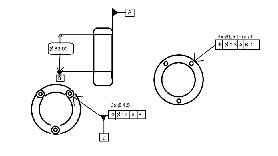
I'm having an issue checking postion on the FCF on the right side of the drawing: 0.3 A | B | C

It's a cylindrical part with three drilled through holes and 3 counterbores on one side, with holes that are offset to the counterbores; they are not centered to the counterbores.

If i'm interpreting the datums right, A is one flat side of the part, B is the center of the main bore, and C is the center of the counterbore.

When I measure everything and report position, the report shows i'm 22mm or so off in the x, and 79 total mm out of position. It seems like it's trying to show position to the center of datum B, which would make sense based on how it's drawn.

Is the feature control frame drawn incorrectly or is something off with my alignment?

Also, am i interpreting it correctly that each counterbore is datum C and each through hole's position must be checked to it's counterbore? If so, how can I change datum C in the middle of a program?

Any help is appreciated, thanks.

Parents
  • The correct interpretation for this is as follows...
    • Datum A is a plane on the RH face.
    • Datum B is the Ø32 bore, measured as a cylinder.
    • Report position of the pattern of 3xØ4.5 counterbores to primary datum A, secondary datum B (no tertiary).
    • Define the pattern of 3xØ4.5 counterbores as datum C.
    • Report position of the pattern of 3xØ1.5 thru holes to primary datum A, secondary datum B, tertiary datum C.
    By reporting the counterbores as a pattern, it controls their relationship to each other as well as the pattern's relationship to the centre bore (B) and orientation to the face (A). By making the pattern of counterbores datum C, when we report the thru holes relative to A|B|C, datum C establishes the rotational control about B, enabling us to control the relationship between the thru holes and counterbores.
    If a tighter control on the relationship between the thru holes and counterbores is required, adding individual concentricity callouts between each pair would be the way to do it (as VPT suggested). However, as it stands, the relationship is controlled by the 0.3 position.

    Example code...

    PLN_A      =FEAT/CONTACT/PLANE/DEFAULT,CARTESIAN,NONE,LEAST_SQR
                THEO/<0,0,0>,<1,0,0>
                ACTL/<0,0,0>,<1,0,0>
                TARG/<0,0,0>,<1,0,0>
                ANGLE VEC=<0,0,1>,RADIAL
                SHOW FEATURE PARAMETERS=NO
                SHOW CONTACT PARAMETERS=NO
    
                DATDEF/A,FEATURES=PLN_A,,
    
    CYL_D32    =FEAT/CONTACT/CYLINDER/DEFAULT,CARTESIAN,IN,LEAST_SQR
                THEO/<0,0,0>,<1,0,0>,32,10
                ACTL/<0,0,0>,<1,0,0>,32,10
                TARG/<0,0,0>,<1,0,0>
                START ANG=0,END ANG=0
                ANGLE VEC=<0,0,1>
                DIRECTION=CCW
                SHOW FEATURE PARAMETERS=NO
                SHOW CONTACT PARAMETERS=NO
    
                DATDEF/B,FEATURES=CYL_D32,,
    
    CYL_CBORE1 =FEAT/CONTACT/CYLINDER/DEFAULT,CARTESIAN,IN,LEAST_SQR
                THEO/<0,0,18.25>,<1,0,0>,4.5,5
                ACTL/<0,0,18.25>,<1,0,0>,4.5,5
                TARG/<0,0,18.25>,<1,0,0>
                START ANG=0,END ANG=0
                ANGLE VEC=<0,0,1>
                DIRECTION=CCW
                SHOW FEATURE PARAMETERS=NO
                SHOW CONTACT PARAMETERS=NO
    CYL_THRU1  =FEAT/CONTACT/CYLINDER/DEFAULT,CARTESIAN,IN,LEAST_SQR
                THEO/<-5,0,18.25>,<1,0,0>,1.5,5
                ACTL/<-5,0,18.25>,<1,0,0>,1.5,5
                TARG/<-5,0,18.25>,<1,0,0>
                START ANG=0,END ANG=0
                ANGLE VEC=<0,0,1>
                DIRECTION=CCW
                SHOW FEATURE PARAMETERS=NO
                SHOW CONTACT PARAMETERS=NO
                WORKPLANE/XPLUS
    CYL_CBORE2 =FEAT/CONTACT/CYLINDER/DEFAULT,CARTESIAN,IN,LEAST_SQR
                THEO/<0,-15.805,-9.125>,<1,0,0>,4.5,5
                ACTL/<0,-15.805,-9.125>,<1,0,0>,4.5,5
                TARG/<0,-15.805,-9.125>,<1,0,0>
                START ANG=0,END ANG=0
                ANGLE VEC=<0,-0.8660254,-0.5>
                DIRECTION=CCW
                SHOW FEATURE PARAMETERS=NO
                SHOW CONTACT PARAMETERS=NO
    CYL_THRU2  =FEAT/CONTACT/CYLINDER/DEFAULT,CARTESIAN,IN,LEAST_SQR
                THEO/<-5,-15.805,-9.125>,<1,0,0>,1.5,5
                ACTL/<-5,-15.805,-9.125>,<1,0,0>,1.5,5
                TARG/<-5,-15.805,-9.125>,<1,0,0>
                START ANG=0,END ANG=0
                ANGLE VEC=<0,-0.8660254,-0.5>
                DIRECTION=CCW
                SHOW FEATURE PARAMETERS=NO
                SHOW CONTACT PARAMETERS=NO
    CYL_CBORE3 =FEAT/CONTACT/CYLINDER/DEFAULT,CARTESIAN,IN,LEAST_SQR
                THEO/<0,15.805,-9.125>,<1,0,0>,4.5,5
                ACTL/<0,15.805,-9.125>,<1,0,0>,4.5,5
                TARG/<0,15.805,-9.125>,<1,0,0>
                START ANG=0,END ANG=0
                ANGLE VEC=<0,0.8660254,-0.5>
                DIRECTION=CCW
                SHOW FEATURE PARAMETERS=NO
                SHOW CONTACT PARAMETERS=NO
    CYL_THRU3  =FEAT/CONTACT/CYLINDER/DEFAULT,CARTESIAN,IN,LEAST_SQR
                THEO/<-5,15.805,-9.125>,<1,0,0>,1.5,5
                ACTL/<-5,15.805,-9.125>,<1,0,0>,1.5,5
                TARG/<-5,15.805,-9.125>,<1,0,0>
                START ANG=0,END ANG=0
                ANGLE VEC=<0,0.8660254,-0.5>
                DIRECTION=CCW
                SHOW FEATURE PARAMETERS=NO
                SHOW CONTACT PARAMETERS=NO
    
    FCFLOC1    =GEOMETRIC_TOLERANCE/STANDARD=ASME Y14.5,SHOWEXPANDED=YES,
                DESCRIPTION=OFF,,
                FEATURE_MATH=DEFAULT,DATUM_MATH=DEFAULT,DISPLAY_COORDS=DRF,
                UNITS=MM,OUTPUT=BOTH,ARROWDENSITY=100,
                SIZE/NOMINAL=4.5,UPPER TOLERANCE=0.2,LOWER TOLERANCE=0.2,
                REPORT_LOCAL_SIZE=OFF,
                  CYL_CBORE1:
                    UAME SIZE:4.500,
                  CYL_CBORE2:
                    UAME SIZE:4.500,
                  CYL_CBORE3:
                    UAME SIZE:4.500,
                SEGMENT_1,POSITION,DIAMETER,0.2,__,__,<len>,__,A,B,__,__,<dat>A,
                TEXT=OFF,CADGRAPH=OFF,REPORTGRAPH=OFF,MULT=10,
                  MEASURED:
                    CYL_CBORE1:0.000,
                    CYL_CBORE2:0.000,
                    CYL_CBORE3:0.000,
                ADD
                DATUMS/REPORTDATUMSIZE=OFF,
                  B(CYL_D32):NOM=32,+Tol=0.01,-Tol=0.01,
                FEATURES/CYL_CBORE1,CYL_CBORE2,CYL_CBORE3,,
    
                DATDEF/C,FEATURES=CYL_CBORE1,CYL_CBORE2,CYL_CBORE3,,
    
    FCFLOC2    =GEOMETRIC_TOLERANCE/STANDARD=ASME Y14.5,SHOWEXPANDED=YES,
                DESCRIPTION=OFF,,
                FEATURE_MATH=DEFAULT,DATUM_MATH=DEFAULT,DISPLAY_COORDS=DRF,
                UNITS=MM,OUTPUT=BOTH,ARROWDENSITY=100,
                SIZE/NOMINAL=1.5,UPPER TOLERANCE=0.2,LOWER TOLERANCE=0.2,
                REPORT_LOCAL_SIZE=OFF,
                  CYL_THRU1:
                    UAME SIZE:1.500,
                  CYL_THRU2:
                    UAME SIZE:1.500,
                  CYL_THRU3:
                    UAME SIZE:1.500,
                SEGMENT_1,POSITION,DIAMETER,0.3,__,__,<len>,__,A,B,__,__,C,__,__,
                TEXT=OFF,CADGRAPH=OFF,REPORTGRAPH=OFF,MULT=10,
                  MEASURED:
                    CYL_THRU1:0.000,
                    CYL_THRU2:0.000,
                    CYL_THRU3:0.000,
                ADD
                DATUMS/REPORTDATUMSIZE=OFF,
                  B(CYL_D32):NOM=32,+Tol=0.01,-Tol=0.01,
                  C(CYL_CBORE1):NOM=4.5,+Tol=0.2,-Tol=0.2,
                  C(CYL_CBORE2):NOM=4.5,+Tol=0.2,-Tol=0.2,
                  C(CYL_CBORE3):NOM=4.5,+Tol=0.2,-Tol=0.2,
                FEATURES/CYL_THRU1,CYL_THRU2,CYL_THRU3,,​
    
Reply
  • The correct interpretation for this is as follows...
    • Datum A is a plane on the RH face.
    • Datum B is the Ø32 bore, measured as a cylinder.
    • Report position of the pattern of 3xØ4.5 counterbores to primary datum A, secondary datum B (no tertiary).
    • Define the pattern of 3xØ4.5 counterbores as datum C.
    • Report position of the pattern of 3xØ1.5 thru holes to primary datum A, secondary datum B, tertiary datum C.
    By reporting the counterbores as a pattern, it controls their relationship to each other as well as the pattern's relationship to the centre bore (B) and orientation to the face (A). By making the pattern of counterbores datum C, when we report the thru holes relative to A|B|C, datum C establishes the rotational control about B, enabling us to control the relationship between the thru holes and counterbores.
    If a tighter control on the relationship between the thru holes and counterbores is required, adding individual concentricity callouts between each pair would be the way to do it (as VPT suggested). However, as it stands, the relationship is controlled by the 0.3 position.

    Example code...

    PLN_A      =FEAT/CONTACT/PLANE/DEFAULT,CARTESIAN,NONE,LEAST_SQR
                THEO/<0,0,0>,<1,0,0>
                ACTL/<0,0,0>,<1,0,0>
                TARG/<0,0,0>,<1,0,0>
                ANGLE VEC=<0,0,1>,RADIAL
                SHOW FEATURE PARAMETERS=NO
                SHOW CONTACT PARAMETERS=NO
    
                DATDEF/A,FEATURES=PLN_A,,
    
    CYL_D32    =FEAT/CONTACT/CYLINDER/DEFAULT,CARTESIAN,IN,LEAST_SQR
                THEO/<0,0,0>,<1,0,0>,32,10
                ACTL/<0,0,0>,<1,0,0>,32,10
                TARG/<0,0,0>,<1,0,0>
                START ANG=0,END ANG=0
                ANGLE VEC=<0,0,1>
                DIRECTION=CCW
                SHOW FEATURE PARAMETERS=NO
                SHOW CONTACT PARAMETERS=NO
    
                DATDEF/B,FEATURES=CYL_D32,,
    
    CYL_CBORE1 =FEAT/CONTACT/CYLINDER/DEFAULT,CARTESIAN,IN,LEAST_SQR
                THEO/<0,0,18.25>,<1,0,0>,4.5,5
                ACTL/<0,0,18.25>,<1,0,0>,4.5,5
                TARG/<0,0,18.25>,<1,0,0>
                START ANG=0,END ANG=0
                ANGLE VEC=<0,0,1>
                DIRECTION=CCW
                SHOW FEATURE PARAMETERS=NO
                SHOW CONTACT PARAMETERS=NO
    CYL_THRU1  =FEAT/CONTACT/CYLINDER/DEFAULT,CARTESIAN,IN,LEAST_SQR
                THEO/<-5,0,18.25>,<1,0,0>,1.5,5
                ACTL/<-5,0,18.25>,<1,0,0>,1.5,5
                TARG/<-5,0,18.25>,<1,0,0>
                START ANG=0,END ANG=0
                ANGLE VEC=<0,0,1>
                DIRECTION=CCW
                SHOW FEATURE PARAMETERS=NO
                SHOW CONTACT PARAMETERS=NO
                WORKPLANE/XPLUS
    CYL_CBORE2 =FEAT/CONTACT/CYLINDER/DEFAULT,CARTESIAN,IN,LEAST_SQR
                THEO/<0,-15.805,-9.125>,<1,0,0>,4.5,5
                ACTL/<0,-15.805,-9.125>,<1,0,0>,4.5,5
                TARG/<0,-15.805,-9.125>,<1,0,0>
                START ANG=0,END ANG=0
                ANGLE VEC=<0,-0.8660254,-0.5>
                DIRECTION=CCW
                SHOW FEATURE PARAMETERS=NO
                SHOW CONTACT PARAMETERS=NO
    CYL_THRU2  =FEAT/CONTACT/CYLINDER/DEFAULT,CARTESIAN,IN,LEAST_SQR
                THEO/<-5,-15.805,-9.125>,<1,0,0>,1.5,5
                ACTL/<-5,-15.805,-9.125>,<1,0,0>,1.5,5
                TARG/<-5,-15.805,-9.125>,<1,0,0>
                START ANG=0,END ANG=0
                ANGLE VEC=<0,-0.8660254,-0.5>
                DIRECTION=CCW
                SHOW FEATURE PARAMETERS=NO
                SHOW CONTACT PARAMETERS=NO
    CYL_CBORE3 =FEAT/CONTACT/CYLINDER/DEFAULT,CARTESIAN,IN,LEAST_SQR
                THEO/<0,15.805,-9.125>,<1,0,0>,4.5,5
                ACTL/<0,15.805,-9.125>,<1,0,0>,4.5,5
                TARG/<0,15.805,-9.125>,<1,0,0>
                START ANG=0,END ANG=0
                ANGLE VEC=<0,0.8660254,-0.5>
                DIRECTION=CCW
                SHOW FEATURE PARAMETERS=NO
                SHOW CONTACT PARAMETERS=NO
    CYL_THRU3  =FEAT/CONTACT/CYLINDER/DEFAULT,CARTESIAN,IN,LEAST_SQR
                THEO/<-5,15.805,-9.125>,<1,0,0>,1.5,5
                ACTL/<-5,15.805,-9.125>,<1,0,0>,1.5,5
                TARG/<-5,15.805,-9.125>,<1,0,0>
                START ANG=0,END ANG=0
                ANGLE VEC=<0,0.8660254,-0.5>
                DIRECTION=CCW
                SHOW FEATURE PARAMETERS=NO
                SHOW CONTACT PARAMETERS=NO
    
    FCFLOC1    =GEOMETRIC_TOLERANCE/STANDARD=ASME Y14.5,SHOWEXPANDED=YES,
                DESCRIPTION=OFF,,
                FEATURE_MATH=DEFAULT,DATUM_MATH=DEFAULT,DISPLAY_COORDS=DRF,
                UNITS=MM,OUTPUT=BOTH,ARROWDENSITY=100,
                SIZE/NOMINAL=4.5,UPPER TOLERANCE=0.2,LOWER TOLERANCE=0.2,
                REPORT_LOCAL_SIZE=OFF,
                  CYL_CBORE1:
                    UAME SIZE:4.500,
                  CYL_CBORE2:
                    UAME SIZE:4.500,
                  CYL_CBORE3:
                    UAME SIZE:4.500,
                SEGMENT_1,POSITION,DIAMETER,0.2,__,__,<len>,__,A,B,__,__,<dat>A,
                TEXT=OFF,CADGRAPH=OFF,REPORTGRAPH=OFF,MULT=10,
                  MEASURED:
                    CYL_CBORE1:0.000,
                    CYL_CBORE2:0.000,
                    CYL_CBORE3:0.000,
                ADD
                DATUMS/REPORTDATUMSIZE=OFF,
                  B(CYL_D32):NOM=32,+Tol=0.01,-Tol=0.01,
                FEATURES/CYL_CBORE1,CYL_CBORE2,CYL_CBORE3,,
    
                DATDEF/C,FEATURES=CYL_CBORE1,CYL_CBORE2,CYL_CBORE3,,
    
    FCFLOC2    =GEOMETRIC_TOLERANCE/STANDARD=ASME Y14.5,SHOWEXPANDED=YES,
                DESCRIPTION=OFF,,
                FEATURE_MATH=DEFAULT,DATUM_MATH=DEFAULT,DISPLAY_COORDS=DRF,
                UNITS=MM,OUTPUT=BOTH,ARROWDENSITY=100,
                SIZE/NOMINAL=1.5,UPPER TOLERANCE=0.2,LOWER TOLERANCE=0.2,
                REPORT_LOCAL_SIZE=OFF,
                  CYL_THRU1:
                    UAME SIZE:1.500,
                  CYL_THRU2:
                    UAME SIZE:1.500,
                  CYL_THRU3:
                    UAME SIZE:1.500,
                SEGMENT_1,POSITION,DIAMETER,0.3,__,__,<len>,__,A,B,__,__,C,__,__,
                TEXT=OFF,CADGRAPH=OFF,REPORTGRAPH=OFF,MULT=10,
                  MEASURED:
                    CYL_THRU1:0.000,
                    CYL_THRU2:0.000,
                    CYL_THRU3:0.000,
                ADD
                DATUMS/REPORTDATUMSIZE=OFF,
                  B(CYL_D32):NOM=32,+Tol=0.01,-Tol=0.01,
                  C(CYL_CBORE1):NOM=4.5,+Tol=0.2,-Tol=0.2,
                  C(CYL_CBORE2):NOM=4.5,+Tol=0.2,-Tol=0.2,
                  C(CYL_CBORE3):NOM=4.5,+Tol=0.2,-Tol=0.2,
                FEATURES/CYL_THRU1,CYL_THRU2,CYL_THRU3,,​
    
Children
No Data