
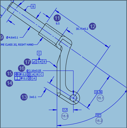

Hello. I'm trying to inspecthe true position of the 3.16mm hole per drawing requirement. I leveled the cyl B to Zplus and rotated the mid plane of datum A to X. Z0 is the plane at the end of culinder B, X0 is the midplane A and Y0 is the Axis of Cylinder B. After the alignment, i measured the datum C plane using Auto plane(6 points spread out) by picking it off the CAD with the A=90B0 probe angle. And 3.16mm hole is measured as a cylinder(4 levels, 5 hits per level, probe angle A90B90). When i build the FCF per drawing and output the result, i'm getting a result thats really out(about 2.2). All the basic dimensions listed on the drawing are close to nominal(7.7 is 7.706, 18.36 is 18.41, the angle 55 is 55.005) and the angulatity is like 0.011).
But when i meaure 6 vector points (again using A90B0 probe angle) and used those points to construct a plane(best fit, least sq) and assign that as datum C, my results are way better and close to what the supplier has listed(0.097).
And whe i changed my hit targets on the auto plane to differnt spots on the plane, i get a different reading but still out of tol. Why is the program giving a different result when a auto plane is used as a datum vs a constructed plane is used as the same datum? what could cause this issue? Any help or advise/tip is really appriciated.
Thank you in advance.
i'm using 2019R2 version
