hexagon logo

Clarification on "Equate Alignments"

Just looking for some clarification. I understand that when you equate one alignment to another, you're supposed to pick up the exact same features in both.

I have a large plate which has features on both sides that need checking. At the moment I'm picking up my CMM bed (Z Plus), the central bore, and a finished edge (XPlus)
My question is, when creating the new alignment after I have flipped over the plate, should I be picking up the granite again or should I be picking up the (now top) surface of the plate? Further, should I be picking everything up in exactly the same way? Meaning, should my XPlus edge now be facing XMinus, and should I call it out that way in the alignment? As written, I'm interpreting it as "Pick up the surface of the plate and align it to ZMinus since in the first orientation it was the granite plate in the ZPlus. Then pick up the finished edge in the same direction you picked it up the first time which is now XMinus. Align the features as ZMinus and XMinus since that would match the original alignment."

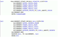
I have a feeling I'm over thinking this pretty hard. I've been fiddling with it for a little while now, but I can't seem to get it to work. I uploaded a picture of the two alignments.

Attached Files
Parents
  • Easiest way to understand it is if you took your finger and held it on the part that you want to use as your initial origin.
    Move the part as necessary (while holding your finger on that same spot).
    Now create a new alignment to match how the part sits on the machine (following your finger).
    Create the equate align afterwards, detailing what you did different.

    As it applies to your specific situation:
    --Initial alignment is a simulated part surface (by leveling to the surface of the machine), which is an inverted vector. you need to match the part's intended 6dof (finger on the spot).
    --Your part's plane is actually a Z- vector, but you are probing in Z+ and leveling in Z+. This is the issue.
    --When you flip the part and measure that true surface, the vector of that part's plane is flipped.
    --You should construct that initial cmm surface plane, then construct a "flipped" vector plane of that plane. That way your initial alignment is relative to the PART.
    When you do this, you won't need to flip the X vector between alignments.

    So:
    Measure cmm plate (Z+).
    create flipped Z- vector plane, from that plane
    create your rotate line
    create your origin circle

    align/level Z- to the flipped Z- plane
    align/rotate X+ about Z
    align/translate x y & z

    move part.

    create top plane
    create same rotation line about the same vector direction, using the same face of the part as before
    create the same origin circle

    align/level Z+ to the top of the part
    align/rotate X+ about Z
    align/translate x y & z

    equate align between the two, and you are set.
Reply
  • Easiest way to understand it is if you took your finger and held it on the part that you want to use as your initial origin.
    Move the part as necessary (while holding your finger on that same spot).
    Now create a new alignment to match how the part sits on the machine (following your finger).
    Create the equate align afterwards, detailing what you did different.

    As it applies to your specific situation:
    --Initial alignment is a simulated part surface (by leveling to the surface of the machine), which is an inverted vector. you need to match the part's intended 6dof (finger on the spot).
    --Your part's plane is actually a Z- vector, but you are probing in Z+ and leveling in Z+. This is the issue.
    --When you flip the part and measure that true surface, the vector of that part's plane is flipped.
    --You should construct that initial cmm surface plane, then construct a "flipped" vector plane of that plane. That way your initial alignment is relative to the PART.
    When you do this, you won't need to flip the X vector between alignments.

    So:
    Measure cmm plate (Z+).
    create flipped Z- vector plane, from that plane
    create your rotate line
    create your origin circle

    align/level Z- to the flipped Z- plane
    align/rotate X+ about Z
    align/translate x y & z

    move part.

    create top plane
    create same rotation line about the same vector direction, using the same face of the part as before
    create the same origin circle

    align/level Z+ to the top of the part
    align/rotate X+ about Z
    align/translate x y & z

    equate align between the two, and you are set.
Children
No Data