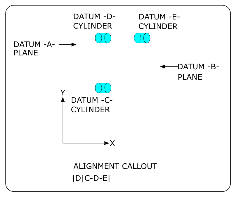
This is where I run into my problem. What, if for example, one of the Z locations of those cylinders is 0.010" off from the other two? The have nothing on the print indicating relationship between those three dowels, other than construction of the plane. They use this alignment scheme on nearly all their parts, some as large as 20 inches long, and their positional tolerancing is from 0.0008"-0.0010" at RFS, regardless the size of the part. In some cases tolerancing will be tight the smaller the part gets. They also require that we send reports with each PPAP part and require absolutely no out of tolerance dimensions on the report. We spend hours in some cases to achieve that, as for some reason the cmm more often than not will get a diameter out of tolerance. Most diameters are toleranced from ±0.00045" - 0.0010" and can vary from 0.500" - 6.000" in size. These tight diameters all get scanned and the roundness ranges from 0.0000"- 0.0001" Most times when verifying diameters with a two point bore gauge, we get them good. I report these using least squared, in Legacy. Reason being, if I switch to use max-inscribed or min-circumscribed, or report with UAME (I may have those backwards as I always forget which one is which) the cmm numbers conflict with the bore gauge, which operators are required to use for in process inspection.
This is the second part of my issue. The customer runs these on their Zeiss to confirm our results. They have failed PPAP's for 0.0003mm, either positional or size! That's the error of the cmm, if I'm not mistaken. Then they have error in their cmm, and there's error in the CNC as well. Here is the last prickly part of this problem, the customer refuses to allow hard gauging to be the arbiter on whether or not the part is correct. All that matters at the end of the day is if they get a green report on their cmm.
I really don't know where to go with these parts anymore. This has been a two year battle and we're not any better off today. We can run the same part 3 times in a row without moving it from the cmm, and get three different results, which understandably causes mistrust with operations. The only thing I can see as potentially having an impact on results is that we run these by jimmy-rigging fixturing on the cmm. A vise, jack screws in some case, whatever we can use to make the part stable. Some of these parts weight 200 pounds, others less than 3 pounds. Am I wrong to believe cmm fixtures designed for the specific parts would yield better accuracy and more reliable consistency?
Thanks in advance for your input.

Attached Files

