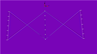
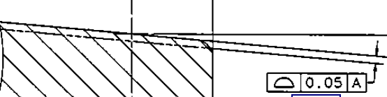
Hi folks, I have a question about how PC-DMIS is handling surface profile. I am using Version 2017 R2, and dimensioning with Xact. The callout is a unilateral profile of .05mm of an outside cone feature, back to Datum-A. Datum-A is an inside cylinder feature. I built the FCF as "PROFILE 0.05 | U | 0 |A". So, when I run my program through simulation, everything should be perfectly on nominal, which everything is, besides the profile. The surface profile is showing a value of .001 on my report. Is PC-DMIS offsetting to the middle of the tolerance zone, or is something weird going on? I will attach the analysis view of the x axis profile and a snippet of the callout. Thanks!
When I build just a regular bilateral profile FCF, the points are lined up with the model. When I build the unilateral profile FCF they are offset to the middle of the zone. I don't typically deal with a lot of unilateral callouts, so I didn't know if this is how PC-DMIS handles it or what.
When I build just a regular bilateral profile FCF, the points are lined up with the model. When I build the unilateral profile FCF they are offset to the middle of the zone. I don't typically deal with a lot of unilateral callouts, so I didn't know if this is how PC-DMIS handles it or what.