hexagon logo

Distance of bottom of theoretical sphere to plane

Good morning PC-DMIS forum,

I am a little newer to CMM programing and hoping I can get some help in this endeavor.


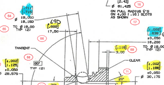
if you can see , the cylinder size (highlighted in blue) is .711-.715 with a theoretical gage ball of .709 going into the cylinder the other dimension highlighted in blue is a distance from the bottom of the theoretical gage ball to a plane.

I have tried making the theoretical sphere using the cylinder and distancing the sphere to the plane but it comes out off, even when i use the "minus radius" button in distance. I believe I can accomplish this measurement, but feel I am missing a piece of the puzzle.

Can anyone here help me solve this issue? it is the last part of a rather robust program the captures most of these dimensions. if it helps the part is orientated so the plane that is being measured is facing up in Z.

Thank you all for helping me out with this.
  • I would construct a work plane perp to the cylinder axis (the actual view), and the a circle tangent to the left side of the cylinder and at the height hidden at the bottom of the view, then dimension the distance between the circle and the plane, minus radius.
  • That sounds promising, I tried figuring out how to implement this and I am unsure how to construct the plane where it is perpendicular to the cylinder, I can only get it parallel for some reason.

    Is there any way you could tell me the steps to achieve this?

    once again, thank you for sharing this knowledge
  • There are differnt solutions, as often :
    Create a generic line (depending on the actual alignment, horizontaly on the view, distance from the axis = hidden dimension + .709)
    Create a local alignment:
    Level X+ on the cylinder, rotate Y to the plane, origin XYZ on the cylinder.
    Then, Z workplane is the right one.
    Create a generic line at Y=CYL.R-.709 (X=0,Z=0, I=1,J=0,K=0)
    Intersect the lines, it should be the center of the circle.
    Create a genric circle at this point, recall the previous alignment and dimension the distance.
  • Another way
    ASSIGN/V1=CROSS(CYL1.IJK,CROSS (PL1.IJK,CYL1.IJK))
    Create a generic line at CYL1.XYZ+(CYL1.R-0.709)*V1
    Intersect this line with the first of the previous post, it's the center if the circle.
  • I think I keep getting close to what you are saying but something is still not working.

    the first way I believe I got really close but at the end, I couldn't intersect the line because PC-DMIS said the lines would never intersect (using the intersect line in construction)

    trying the second method I once again feel I have gotten really close, I just can't seem to type out the generic line as stated but feel if I can just type that out in the command window, this whole thing would work every time I start to type in "Generic, LINE" it automatically populates with " dependent, creastisian" (defiantly spelled that wrong) so i can not create the generic line as it is laid out.

    I apologize if I am missing something sort of basic, this part is probably one of the more complicated parts I ever had to program but if I can get this part right, it'll decrease inspection tie by hours and maybe even days.

    thank you for your patience
  • In the first way, create a generic plane instead of the first Line.